¦ ¦ ¦ ¦ ¦
ENVIS Technical Report 143,   May 2018
WASTE MANAGEMENT
Energy & Wetlands Research Group, Centre for Ecological Sciences, Indian Institute of Science, Bangalore, Karnataka, 560 012, India.
E Mail: tvr@iisc.ac.in; bharathh@iisc.ac.in; setturb@iisc.ac.in; svinay@iisc.ac.in Tel: 91-080-22933099, 2293 3503 extn 101, 107, 113
Basic Spatial Analysis

Analysis of Spatial Information
Even though most of the real world can be observed with the naked eye, it is often difficult to interpret and systematize what is observed. It becomes even more difficult when the image of that reality is stored in digital form as map data and attribute tables. To bring out the patterns, connections, and possibly, the causes of variations in the data, various computer-based techniques are applied to analyse the data. Spatial analysis techniques are an attempt to imitate what concerns the human brain (i.e., to create an understandable image of reality). These are the techniques discussed in this and the following chapter.

Technology can still only help to a limited extent, however. Stating problems and delineating the approaches to solutions together comprise one of the most difficult steps in GIS analysing. This has to be solved by the individual user or operator before the technology can be put into use, based on his or her professional knowledge in the fields of agriculture, environmental protection, planning, and so on, supplemented with knowledge of GIS. Analysing data normally comprises two principal phases:

  • Choice of data

  • Analyses of the data chosen

All GISs provide functions for analyses of data chosen and for storing the results of such analyses. Data may be selected according to

  • Geographical location

  • Thematic content

     Most GISs permit defining the criteria for selection. These are often based in SQL or are in menus with provisions for generating SQL queries. Some GISs provide predefined selection criteria; other systems use a macro language to set up the selection criteria. Specific systems have predefined menus dedicated to the relevant applications. In most systems, selection criteria may be stored for subsequent use.
Data may be analysed at various levels:

  • Data in attribute tables are sorted for presentation in reports or for use in other computer systems.

  • Operations are performed on geometric data, either in search mode or for computational purposes.

  • Arithmetic, Boolean, and statistical operations are performed in attribute tables.

  • Geometry and attribute tables are used jointly to:

    • Compile new sets of data, based on original and derived attributes

    • Compile new sets of data based on geographical relationships.

    Within each of these levels, the operations used may be logical, arithmetic, geometric, statistical, or a combination of two or more of these four types. Operations may be performed on individual points or on areas, and may involve considerations of proximity or of changes over time. Numerous operations may be performed on line networks. The more important commands are discussed below. The functions implemented vary from one GIS to another, and some GISs contain functions not discussed here.


Logic Operations: Logical searches in databases normally employ set algebra or Boolean algebra. Set algebra uses the three operators equal to, greater than, and less than, and combinations thereof:
=, >, <, ³, £, <>
These operators are included under SQL.
Practical applications include:

  • Identifying extrema, such as finding attribute minima or maxima within various polygons and, as a result, delineating a new thematic layer (new row in the attribute table)

  • Selection or isolation, where particular values are selected for subsequent ranking in a new thematic layer

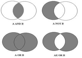
Boolean algebra uses the AND, OR, NOR, and NOT operators to test whether a statement is true or false. AND, OR, and NOT are used in SQL. For two items, A and B, we might have any of the following statements:
A AND B, A OR B, A NOR B, A NOT B


Figure 5.1: Logical operations showing in a Venn diagram


Such statements may be illustrated in a Venn diagram, which is a schematic representation of a set in which magnitudes illustrated by surfaces are superimposed, as shown in Figure 5.1. The shaded areas represent true statements. This technique is well suited to analysing geographical data. For example, assigning A to potentially productive forest tracts and B to known grazing areas can illuminate potential conflicts between forestry and cattle farming. The tests A AND B on the two operands will identify conflict areas that can be assigned special symbols and drawn on maps. Logic operations are particularly powerful when the relationships are complex. In GIS, logic operations may be performed simultaneously on more than two themes and involve several operators.

General Arithmetic Operations
Arithmetic operations are performed on both attribute and geometric data. All GISs support the customary arithmetic operations of addition, substraction, multiplication, division, exponential, square root, and the trigonometric functions:
+, -, ×, /, n, Ö, sin, cos, tan

these operators may be used for many purposes, including assigning new thematic codes. Typical examples include:

  •  Reclassification of soil types, in which areas are to be converted from square kilometers to hectares by dividing all area figures by 10.

  •  Conversion of distances along roads to driving times, by dividing all distances by a specified average vehicle speed. The result is a new set of attributes that are useful in transportation planning.

Arithmetic functions are used in all geometric computations involving coordinates, as in calculating distances, areas, volumes, and directions.

General Statistical Operations
Statistical operations are performed primarily on attribute data, but may also be effected on some types of geometric data. Most GISs support a range of statistical operations, including sum, maxima, minima, average, weighted average, frequency distribution, bi-directional comparison, standard deviation, multivariate, and others. The computation of averages requires averaging two or more attribute values and stating the result as a new attribute. Frequency distributions are used to compile histograms, charts comprising rectangles whose areas are proportional to relative frequencies and whose widths are proportional to class intervals. The data used to draw a histogram may also be employed to plot a curve. Other statistical operations in common use include least-squares computations of transformation parameters from regression models, with the standard deviation as an expression of accuracy. Bidirectional comparison involves point-by-point correlation of two themes to produce a new statistical thematic layer and hence a new attribute.
Satellite data are usually analysed statistically in dedicated image processing systems, which are often connected to GIS facilities. Some vector GISs support image processing. Multivariate operations, such as cluster analyses, are vital in image analyses. These operations assign new classes to entities on the basis of statistical selection criteria. Pattern recognition based on statistical models is incorporated in some GISs.

Integrated Processing of Geometry and Attributes

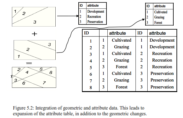
One of the simpler forms of integrated processing of geometry and attributes is to point to the location of a building displayed on screen and request retrieval of all information stored on the building. On receiving the query, the GIS searches the map database to find the building corresponding to the coordinates that have been pinpointed. Using the building ID number stored with the coordinates, the system then searches the attribute database for all available information, which can then be displayed or printed out. More advanced integrated processing is also based on the condition that each object type (cultivated land, deciduous forest, protected area, etc.) is represented both in geometry and in an attribute table. The geometry concerned may be likened to a single thematic map. Single maps may then be superimposed to integrate with each other and thus  produce a multithematic map containing information from each of the initial thematic maps. The integrated map comprises comparable units [integrated terrain units (ITUs)] and a new attribute table is compiled, as illustrated in Figure 5.2. Arithmetic, logical, and statistical operations may be performed in the new attribute table. The geometry and the attributes may then be used to compile a new thematic map.

Overlay: Overlay is used in data integration and is a technical process, the results of which can be used in realistic forms of spatial analysis.

Polygon overlay


Figure 5.3


Polygon overlay is a spatial operation in which a first thematic layer containing polygons is superimposed onto another to form a new thematic layer with new polygons. This technique maybe likened to placing map overlays on top of each other on a light table (Figure 5.3). The corners of each new polygon are at the intersections of the borders of the original polygons; hence computing the coordinates of border intersections is a vital function in polygon overlay.

Points on polygons:

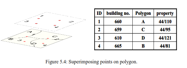
Just as polygons maybe superimposed on other polygons, so may points be superimposed on polygons (Figure 5.4). The points are then assigned the attributes of the polygons upon which they are superimposed. The relevant geometric operation means that points must be associated within polygons. One approach requires computing the intersection of a polygon border with parallel lines through points. Attribute tables are updated after all points are associated with polygons.

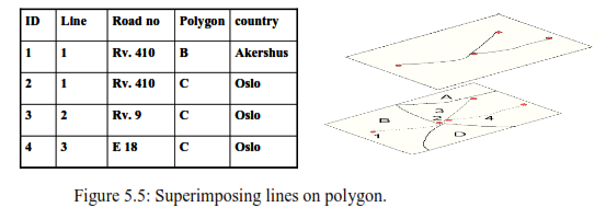
Lines on polygons: Lines may also be superimposed on polygons (Figure 5.5), with the result that a new set of lines contains attributes of both the original lines and the polygons. These particular computations are similar to those used in polygon overlay: intersections are computed, nodes and links are formed, topology is established, and attribute tables are updated.


Buffer Zones

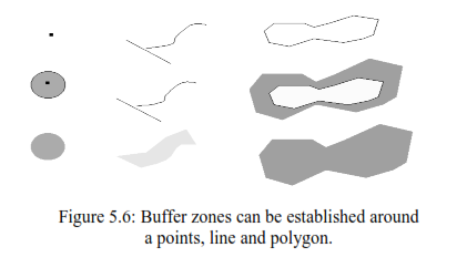
Buffer zones are used to define spatial proximity (Figure 5.6). These comprise one or more polygons of a prescribed extent around points, lines, or areas. The new polygons have the attributes of the original objects. Many GISs support the automatic compilation of buffer zones. Here, the operator interaction usually consists of keying in a specific zone parameters, such as stipulating a 50-m zone width or either side of a road. The creation of a buffer zone is not in itself an analysis, but the new polygons that are created can be used in analysis. Buffer zone polygons maybe processed in the same way as polygons generated during operations such as overlay, arithmetic, logical, and statistical computations in which attribute values come within the respective zones.


Raster Data Overlay

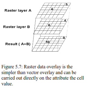
Raster data may also be overlaid. Indeed, raster overlay is often more efficient than vector overlay (Figure 5.7). The positions of the overlaid thematic layers need be tested only to see whether or not they contain cell values. The resultant cell-to-cell comparison presupposes that all cells in each thematic layer are queried, regardless of their values. The total number of cells therefore has an effect on processing time. The new composite cells are assigned attributes composed of those from the original cells. These new cells are registered as a new thematic layer.
Raster data consist of equally spaced cells of equal size (assuming that the various thematic layers cover the same area or have been modified to do so). Consequently, there is no formation of smaller erroneous polygons as with vector data overlays, and there is no need to distinguish between polygons, lines, and points, because all raster data comprise cells. In raster data, attributes are not usually listed in tables as in vector data, but are represented by thematic layers. Therefore, arithmetic operations and some logical and statistical operations may be performed directly during the overlay process; two thematic layers may be combined, subtracted, multiplied, and so on. If for example, an attribute of volume in liters is to be modified to decilitres, the thematic layer of volumes merely needs to be multiplied by 10 in each cell of an ancillary thematic layer.


The arithmetic operations on two thematic layers, A and B, produce a new thematic layer, C, through the operations
C=A + B, C=A –B, C=A/B, C=A x B
Typical logical operations might be
If A> 100, C =10; otherwise C= 0
Or
C= max. (or min.) of A nad B
Some GISs support logical operations in the resultant Clayer but not directly in the original A and B layers.
As raster overlay is far more efficient than vector overlay, many GISs support functions for manipulating both raster and vector data. Vector data may be converted to raster data in order that overlaying can be performed, and results can then be converted back to vector form.

Procedures in integrated Data analysis:


Integrated data analysis follows fixed procedures:

  • Starting the problem.

  • Adapt the data for geometric operation.

  • Perform the geometric operation.

  • Adapt attributes for the analysis.

  • Perform the analysis.

  • Evaluate the results.

  • Redefine and instigate new analysis if needed.   

Stating the problem: It involves defining the problem, and the criteria to be used in the analysis.

Adapting the data for geometric operations: Data available from a database must be modified before they can be used for geometric operations.

Performing the geometric operations: Geometric operations, employed to sort out the objects to be analysed include specification of the buffer zones, overlaying, search and retrieval, joining polygons, and other operations.
For each task the geometric operations must be defined on the basis of the analytic criteria involved.  
Adapting attributes for analysis: Attribute data must also be processed before analysis.
Attribute table must contain an adequate number of empty rows and columns for new entries.

Performing attributes analysis: arithmetic, logical and statistical operations are performed on attribute data associated with the object chosen in geometric phase.

Evaluating the results: The results must be evaluated for their trustworthiness
Redefinitions and instigating new analysis: Unacceptable results must be modified or the analysis that produced them improved and performed again.

Presenting the final results: Analytical results are best presented in easily read maps and written reports.    

• Selection of a recreational area that can provide a wilderness experience:
Step 1:
a) Remoteness, at a specified distance from the manufactured facilities
b) Reasonable accessibility
c) lakes and streams
d) varied topography
e) A variety of vegetation
Step 2: Map data or attribute data or both be modified by clipping a selected area out of a map database, modifying the area from hectares to kilometers, etc.

Step3: a) In the location of the recreational area broad buffer  zones may be set up around the roads and other  manufacturing facilities.
b) The untouched zones can areas outside these zones may then be overlaid with vegetation, hydrology and other relevant data. 

Step 4: A new attribute labeled “suitable characteristic ” may be complied to hold codes that indicate the degree of suitability of various combinations of thematic layers.

Step 5: Analysis may be performed to identify all areas outside the buffer zone around manufactured facilities. another analysis might aim to select areas classified as moderately hilly, etc. 

Step 6: Evaluation is done and if require modifications are made at suitable stage


E-mail     |     Sahyadri     |     ENVIS     |     GRASS     |     Energy     |     CES     |     CST     |     CiSTUP     |     IISc     |     E-mail