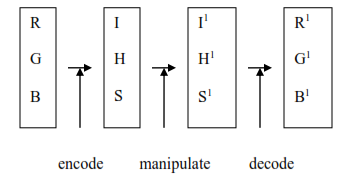
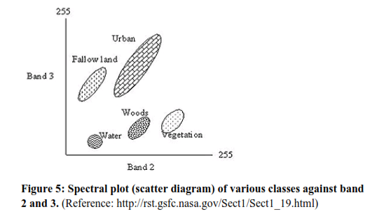
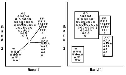
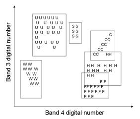
¦ ¦ ¦ ¦ ¦
ENVIS Technical Report 143,   May 2018
WASTE MANAGEMENT
Energy & Wetlands Research Group, Centre for Ecological Sciences, Indian Institute of Science, Bangalore, Karnataka, 560 012, India.
E Mail: tvr@iisc.ac.in; bharathh@iisc.ac.in; setturb@iisc.ac.in; svinay@iisc.ac.in Tel: 91-080-22933099, 2293 3503 extn 101, 107, 113
Introduction to Remote Sensing and Digital Image Processing

Of all the various data sources used in GIS, one of the most important is undoubtedly that provided by remote sensing. Through the use of satellites, we now have a continuing program of data acquisition for the entire world with time frames ranging from a couple of weeks to a matter of hours. Very importantly, we also now have access to remotely sensed images in digital form, allowing rapid integration of the results of remote sensing analysis into a GIS
Because of the extreme importance of remote sensing as a data input to GIS, it has become necessary for GIS analysts (particularly those involved in natural resource applications) to gain a strong familiarity with Image processing system (IPS). Consequently, this chapter gives an overview of this important technology and its integration with GIS.

Definition

Remote sensing can be defined as any process whereby information is gathered about an object, area or phenomenon without being in contact with it. Our eyes are an excellent example of a remote sensing device. We are able to gather information about our surroundings by gauging the amount and nature of the reflectance of visible light energy from some external source (such as sun or a light bulb) as it reflects off objects in our field of view. Contrast with this thermometer, which must be in contact with the phenomenon it measures, and thus is not a remote sensing device.
Given this rather general definition, the term remote sensing has come to be associated more specifically with the gauging of interactions between earth surface materials and electromagnetic energy. However, any such attempt at a more specific definition becomes difficult, since it is not always the natural environment that is sensed (e.g., art conservation applications), the energy type is not always electromagnetic (e.g., sonar) and some procedures gauge natural energy emissions (e.g., thermal infrared) rather than interactions with energy from an independent source.
Basic Process involved-

  1. Data Acquisition

  2. Data Analysis


Data Acquisition -

Propagation of energy through the atmosphere


Energy interaction with the earth surface


Retransmission of energy through the earth’s surface


Sensing systems

Sensing Products (pictorial/digital)

Data analysis

  • Interpretation and Analysis (application in various fields such as land use, geology, hydrology, vegetation, soil )

  • Reference data are used to assist in the analysis and interpretation.


Fundamental Considerations

Energy Source

Sensors can be divided into two broad groups: passive and active. Passive sensors measure ambient levels of existing sources of energy, while active ones provide their own source of energy. The majority of remote sensing is done with passive sensors, for which the sun is the major energy source. The earliest example of this is photography. With airborne cameras we have long been able to measure and record the reflection of light off earth features. While aerial photography is still a major form of remote sensing, newer solid-state technologies have extended capabilities for viewing in the visible and near-infrared wavelengths to include longer wavelength solar radiation as well. However, not all passive sensors use energy from the sun. Thermal infrared and passive microwave sensors both measure natural earth energy emissions. Thus the passive sensors are simply those that do not themselves supply the energy being detected.
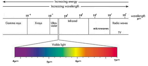
By contrast, active sensors provide their own source of energy. The most familiar form of this is flash photography. However, in environmental and mapping applications, the best example is RADAR. RADAR systems emit energy in the microwave region of the electromagnetic spectrum Fig 3.1. This reflection of that energy by earth surface materials is then measured to produce an image of the area sensed.


Wavelength


As indicated, most remote sensing devices make use of electromagnetic energy. However, the electromagnetic spectrum is very broad and not all wavelengths are equally effective for remote sensing purposes. Furthermore, not all have significant interactions with earth surface materials of interest to us. Fig 3.1 illustrates the electromagnetic spectrum. The atmosphere itself causes significant absorption and/ or scattering of the very shortest wavelengths. In addition, the glass lenses of many sensors also cause significant absorption of shorter wavelengths such as ultraviolet (UV). Even here, the blue wavelengths undergo substancial attenuation by atmospheric scattering, and are thus often left out in remotely sensed images. However, the green, red, and near-infrared (IR) wavelengths all provide good opportunities for gauging earth surface interactions without significant interference by the atmosphere. In addition, these regions provide important clues to the nature of many earth surface materials. Chlorophyll, for example, is a very strong absorber of red visible wavelengths, while the near-infrared wavelengths provide important clues to the structures of plant leaves. As a result, the bulk of remotely sensed images used in GIS-related applications are taken in these regions.
Extending into the middle and thermal infrared regions, a variety of good windows can be found. The longer of the middle infrared wavelengths have proven to be useful in a number of geological applications. The thermal regions have proven to be very useful for monitoring not only the obvious cases of the spatial distribution of heat from industrial activity, but a broad set of applications ranging from fire monitoring to animal distribution studies to soil moisture conditions.
After the thermal IR, the next area of major significance in environmental remote sensing is in the microwave region. A number of important windows exist in this region and are of particular importance for the use of active radar imaging. The texture of earth surface materials causes significant interactions with several of the microwave wavelength regions. This can thus be used as a supplement to information gained in other wavelengths, and also offers the significant advantage of being usable at night (because as an active system it is independent of solar radiation) and in regions of persistent cloud cover (since radar wavelengths are not significantly affected by clouds).

Interaction Mechanisms


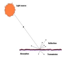
Fig 3.2: Interaction mechanism between EM energy and material.


When electromagnetic energy strikes a material, three types of interaction can follow: reflection, absorption, and/ or transmission (figure 3-2). Our main concern is with the reflected portion since it is usually this which is returned to the sensor system. Exactly how much is reflected will vary and will depend upon the nature of the material and where in the electromagnetic spectrum our measurement is being taken. As a result, if we look at the nature of this reflected component over a range of wavelengths, we can characterise the result as a spectral response pattern.

Electromagnetic Radiation

Nuclear reactions within the sun produces spectrum of electromagnetic radiation which is transmitted through the space without major changes. Examples of electromagnetic radiation are heat, radio waves, UV rays, X-rays

Waves obeys general equation –
C = ν x λ
C = 3 x 10⁸  m/s
ν  = frequency
λ = wavelength
Wavelength –The distance between one wave crest to the next
Frequency- Number of crests passing a fixed point at a given period of time
Amplitude-Equivalent to height of each peak

Electromagnetic waves are characterized by their wavelength location on electromagnetic spectrum. Unit of wavelength is µm.
1µm = 1 x10⁻⁶ m

UV

Visible(µm)

0.8-0.9  (µm)

0.9-1.3 (µm)

1.3-14 (µm)

Microwaves

0.4-0.5

0.5-0.6

0.6-0.7

Blue

Green

Red

Near IR

Mid IR

Far IR

Interaction with surfaces-As electromagnetic energy reaches the earth’s surface it must be reflected, absorbed or transmitted.

The proportions depends on-

  • Nature of surface

  • Wavelength of energy

  • Angle of illumination

Reflection-When ray of light is redirected when it strikes a non transparent surface.

Transmission -When radiation passes through a substance without significant attenuation.

Fluorescence -When an object is illuminated with radiation at one wavelength and it emits radiation at another wavelength.

Electromagnetic waves are categorized by their wavelength location in electromagnetic spectrum. Electromagnetic radiation is composed of many discrete units called photons or quanta.

                            Q = h ν
Q = energy of quantum, Joules (J)
h = Plank’s constant
ν = Frequency

Q= h (c/ λ)
Q = 1/ λ ie, the longer the wavelength involved the lower is its energy content. All matter at temperature above absolute zero continuously emits electromagnetic radiation.

 Stefen-Boltzmann Law- The amount of energy a body radiates is the function of its surface temperature.
M = σ T4
M = total radiant exitance from the surface of a material
σ = Stefen-Boltzmann constant, 5.6697 X 10⁻⁸ Wm-2K-4
T = absolute temperature (K) of the emitting material
Total energy emitted from an object varies as T4  and increase very rapidly as temperature increases.

The rate at which photons (quanta) strike a surface is called radiant flux (øc ) measured in Watts.
Irradiance (Ee) is defined as radiant flux per unit area.

A blackbody is a hypothetical source of energy that behaves in an idealized manner. It absorbs all incident radiation, none of the radiation is reflected.

Kirchoff’s Law states that-The ratio of emitted radiation to the absorbed radiation flux is same for all black bodies at the same temperature.

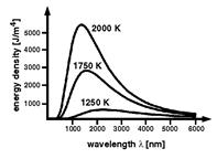
Wien’s Displacement law- specifies relationship between wavelength of radiation emitted and temperature of a black body.
λ = 2897.8 / T
λ = wavelength at which temperature is maximum
T = absolute temperature (K)


Figure 1: Spectral distribution of energy radiated from blackbodies of various temperatures. (Reference: http://itl.chem.ufl.edu/4412_aa/origins.html)


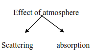
Energy interaction in the atmosphere
The net effect of atmosphere varies with the following factors-

  • Path length

  • Magnitude of energy signal being sensed

  • Atmospheric conditions present

  • Wavelength involved


Scattering

Reyleigh Scatter-When radiation interacts with the atmospheric molecules and other tiny molecules which are smaller in diameter than wavelength of interacting radiation then Reyleigh scatter is inversely proportional to the fourth power of the wavelength.

When sunlight interacts with the earth’s atmosphere then it scatters shorter wave (blue) wavelengths more dominantly than other visible wavelengths. During sunrise and sunset sun’s ray travel in a longer atmospheric path than during midday. With longer wave path the scatter of shorter wavelength is so complete that we see longer wavelengths of orange and red.

Mie Scatter-When atmospheric particle diameter is equal to the wavelength of energy being sensed. Water vapour and dust are the major causes of Mie Scatter.

Non selective Scatter-When the diameter of particles causing scatter are much larger than the wavelength of energy being sensed. Water droplets have diameter in the range 5-100µm and scatters all visible and near to mid IR wavelengths equally. In visible wavelengths equal quantities of blue, green, red light are scattered hence fog appears white.

Absorption: Absorption of radiation occurs when atmosphere prevents or strongly attenuates transmission or radiation of energy through the atmosphere. Water vapour, carbon di oxide, ozone are the most efficient absorber of solar radiation.

Ozone is formed when oxygen reacts with UV radiation. It lies 20-30 Km in the stratosphere. Carbon di oxide is important in remote sensing because it is effective in absorbing radiation in mid and far IR rays. Its strongest absorption occurs in the range 13-17.5µm. Water vapour present in the atmosphere is 0-3% by volume. Two of the most important regions are several bands between 5.5 to 7.0µm and above 27.0µm.Absorption in these region can exceed 80%if the atmosphere contains considerable amount of water vapour. The wavelength at which atmosphere is particularly transmissive of energy are referred as atmospheric windows.

Energy interactions with Earth surface features-
Applying Principle of conservation of Energy, EI (λ) =  ER (λ) +  EA (λ)+  ET (λ)
EI = incident energy; ER = reflected energy; EA=absorbed energy; ET = transmitted energy

ER (λ) = EI (λ) - [ EA (λ) +  ET (λ)]
Reflected energy is equal to the energy incident on a given feature reduced by the energy that is either absorbed or transmitted by that feature.

The geometric manner in which an object reflects energy is function of surface roughness of the object.

Specular reflectors- Flat surface in which angle of reflection is equal to the angle of incidence.

Diffuse reflectors-rough surface that reflects uniformly in all directions.


Spectral response Patterns: A spectral response pattern is sometimes called a signature. It is a description (often in the form of a graph) of the degree to which energy is reflected in different regions of the spectrum. Most humans are very familiar with spectral response patterns since they are equivalent to the human concept of colour. The bright red reflectance pattern fig 3.3, for example, might be that produced by a piece of paper printed with a red ink. Here, the ink is designed to alter the white light that shines upon it and absorb the blue and green wavelengths. What is left, then, are the red wavelengths which reflect off the surface of the paper back to the sensing system (the eye). The high return of red wavelengths indicates a bright red, whereas the low return of green wavelengths in the second example suggests that it will appear quite dark. 


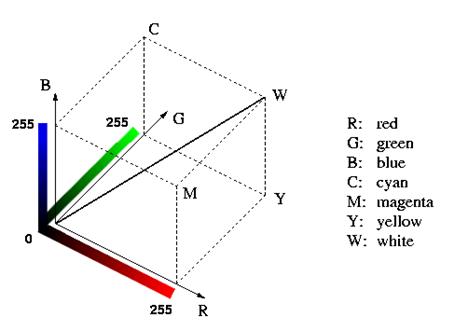
The eye is able to sense spectral response patterns because it is truly a multi-spectral sensor (i.e., it senses in more than one place in the spectrum). Although the actual functioning of the eye is quite complex, it does in fact have three separate types of detectors that can usefully be thought of as responding to the red, green and blue wavelength regions. These are the additive primary colours, and the eye responds to mixtures of these three to yield a sensation of other hues. For example, the colour perceived would be a yellow as a result of mixing a red and green. However, it is important to recognize that this is simply our phenomenological perception of a spectral response pattern. Consider, for example, the fig 3.4. Here we have reflectance in both the blue and red regions of the visible spectrum. This is a bimodal distribution, and thus technically not a specific hue in the spectrum. However, we would perceive this to be a purple! Purple  (a colour between violet and red) does not exist in nature (i.e., as a hue- a distinctive dominant wavelength). It is very real in our perception, however. Purple is simply our perception of a bimodal pattern involving a non-adjacent pair of primary hues.


In the early days of remote sensing, it was believed (more correctly hoped) that each earth surface material would have a distinctive spectral response pattern that would allow it to be reliably detected by visual or digital means. However, as our common experience with colour would suggest, in reality this is often not the case fig 3.5. For example, two species of trees may have quite a different coloration at one time of the year and quite a similar one at another.

Finding distinctive spectral response patterns is the key to most procedures for computer-assisted interpretation of remotely sensed imagery. This task is rarely trivial. Rather, the analyst must find the combination of spectral bands and the time of year at which distinctive patterns can be found for each of the information classes of interest.

For example, Fig 3.6 shows an idealized spectral response pattern for vegetation along with those of water and dry bare soil. The strong absorption by leaf pigments (particularly chlorophyll for purposes of photosynthesis) in the blue and red regions of the visible portion of the spectrum leads to the characteristic green appearance of healthy vegetation. However, while this signature is distinctly different from most non-vegetated surfaces, it is not very capable of distinguishing between species of vegetation- most will have a similar colour of green at full maturation. In the near-infrared, however, we find a much higher return from vegetated surfaces because of scattering within the fleshy mesophyllic layer of the leaves. Plant pigments do not absorb energy in this region, and thus the scattering, combined with the multiplying effect of a full canopy of leaves, leads to high reflectance will depend highly on the internal structure of leaves (e.g., broadleaf versus needle). As a result, significant differences between species can often be detected in this region. Similarly, moving into the middle infrared region we see a significant dip in the spectral response pattern that is associated with leaf moisture. This is, again, an area where significant differences can arise between mature species. Applications looking for optimal differentiation between species, therefore, will typically involve both the near and middle infrared regions and will use imagery taken well into the development cycle.

Data acquisition and interpretation
Detection of electromagnetic energy-   Photographically
Electronically

Photography-Chemical reaction on the surface of light sensitive film to detect energy variation within a scene.
Electronic sensors generate an electrical signal that corresponds to the energy variations in the original scene.

Analogue to digital conversion Process: Digital Numbers are positive integers that results from quantisizing the original electrical signal from sensor into positive integer value by a process called Analogue to digital conversion Process. The original electrical signal from sensor is continuous analogue signal. This signal is sampled at a set time interval (ΔT) and recorded numerically at each sample points (a,b,c,d). DN output are the integers ranging from 0-255. In numerical format, image data can readily be analyzed with the aid of a computer.

Reference data is used for the following purpose-

  • Analysis and interpretation of remote sensed data
  • To calibrate a sensor
  • Verify information extracted from remote sensing data


Reference data are of two types-

  1. Time critical-Where ground conditions changes rapidly with time such as analysis of vegetation conditions, water pollution events.
  2. Time stable-Where materials under observation donot change appreciably with time such as geologic application.

Spectral Response Pattern- Water and vegetation might reflect equally in visible light but these features are always separable in IR radiations.
Spectral responses measured by remote sensors over various features permits the assessment of type and condition of feature and are referred as spectral signatures. The physical radiation measurement at those wavelengths is referred as spectral response. Spectral signatures are absolute and unique. Spectral response pattern may be quantitative but not unique. This variability causes various problems if the objective is to identify various earth features. Therefore it is important to identify the nature of ground area one is looking at to minimize spectral variability.

Spectro radiometer- This device measures function of wavelength of the energy coming from an object within its view.

Bidirectional reflectance Distribution Function –Mathematical description of how reflectance varies for all combinations of illuminations and viewing angles of a given wavelength.

Three models of Remote Sensing-  The reflection of solar radiation from the earth’s surface is recorded. Aerial camera mainly uses energy in the visible and near IR portions of the spectrum.

Passive Remote Sensing - The radiation emitted from the earth’s surface is recorded. Emitted energy is the strongest in the far IR spectrum. Emitted energy from the earth’s surface is mainly derived from the short wavelength energy from the sun which is absorbed by the earth’s surface and reradiated at a longer wavelength. Other sources of emitted radiations are geothermal energy, heat from steam pipes, power plants.

Active Remote Sensing - Active sensors provide their own energy and therefore they are independent of terrestrial and solar radiation. Camera with a flash is an example of active remote sensing.


Ideal Remote sensing system

  • Uniform energy source
  • Non-interfering atmosphere-where atmosphere would not modify the energy from the source in any manner either on the way to the earth surface or coming from it.
  • Energy matter interaction unique to each and every earth surface.
  • Super sensor - sensor highly sensitive to all wavelength
  • A real-time data processing and supply – Each data observation would be recognized as being unique to the particular terrain element from which it came. The derived data would provide insight into the physical, chemical and biological state of each feature of interest.

Photography
Basic concept of camera

  • Lens to focus light on the film
  • Light sensitive film to record the object
  • Shutter that controls the entry of light into camera
  • Camera body a light tight enclosure

Lens-It gathers light and focuses it on film. The sizes, shapes, arrangement and composition of lenses are designed to control the bending of light rays to maintain colour balance and to minimize optical distortions. Imperfection in lens shape contributes to spherical aberration, a source of error that distorts the image and causes loss of clarity.

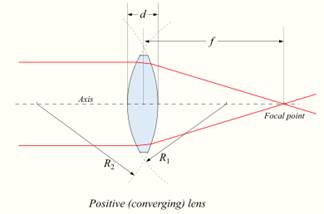
Simple Positive lens- Equal curvature on both the sides. Light rays are refracted from both the edges to form image.

Compound lens-Formed of separate lenses of varied sizes, shapes and properties.

Optical axis-joins the centre of curvature of both sides of lens.

Image Principle Plane-Plane passing through the centre of lens.

Nodal point-where image principal plane intersects optical axis

Focal Point-Parallel light rays pass through the lens and are brought to the focus at the focal point.

Focal plane-A plane passing through the focal point parallel to the image principal plane.

 Focal length-It is the distance from centre of the lens to the focal point.


Figure 3.7: Lens. (Reference: wikipedia.org/wiki/Lens_(optics))

For aerial cameras, the scene to be photographed is at such a large distance that focus can be fixed at infinity. For a given lens the focal length is not identical for all the wavelengths. Blue is brought to the focal point at a shorter distance than Red or IR wavelength. This is the source of chromatic aberration.

Aperture Stop-It is positioned near centre of compound lens which controls the intensity of light at focal plane. Manipulation in aperture stop controls the brightness of image.

Shutter- controls the length of time the film is exposed to light.

Film magazine-Light tight container that holds the supply of a film.

Supply spool-holding several hundred feet of unexposed aerial film

Take up spool- accept exposed film

Lens cone-supports the lens and filters and holds them in correct position. Common focal length for typical aerial cameras is 150mm, 300mm, 450mm.

Kinds of cameras-

Reconnaissance camera

  • Military use
  • Donot have geometric accuracy
  • Ability to take photograph at high speed
  • Ability to take photograph in unfavourable light conditions and low speed

     Strip camera

  • It acquires images by moving film past a fixed slit that serves as shutter.
  • The speed of the film movement as it passes through the shutter is coordinated with the speed of aircraft movement.
  • High quality image from planes flying at high speed and low altitude.

     Panoramic cameras

  • It is designed to record a very wide field of view.
  • Photograph from panoramic camera show a narrow strip of terrain that is perpendicular to the flight track from horizon to horizon.
  • Serious geometric distortions
  • Useful for large area they represents

Black and white aerial Films
Major components
Base- a thin (40-100µm), flexible transparent material that holds a light sensitive coating (photographic emulsion).

Emulsion-Modern emulsion consists of Silver halide (silver bromide-95% and silver iodide-5%).
Silver halide crystals are insoluble and donot adhere to the base. Silver halide crystals are hold in suspension by gelatin and are evenly spread. Gelatin is transparent, porous and absorbs light rays when light strikes the emulsion.

Physical properties of Silver halide-

  • Extremely small
  •  irregular in shape
  • sharp edges

The finer the size of the grain the finer details can be recorded. Below the emulsion is subbing layer to ensure that it adhere to the base. On the reverse side of the base there is antihalation backing that absorbs light that passes through the emulsion and the base and prevents reflection back to the emulsion. 

Process-When the shutter opens it allows the light to enter and strike the emulsion .Silver halide crystals are very small and even a small area of a film contains thousands of crystals. When light strikes a crystal then it converts small portion of crystals into metallic silver. The more intense the light striking a portion of the film the greater is the number of crystals affected.

Development-The process of bathing the exposed film in an alkaline chemical developer that reduces the silver halide grain that exposed to the light. Fixer is applied to dissolve or remove unexposed silver halide grains. After development and fixing the resulting image is a negative representation of a scene. Those areas which were brightest in the scene are represented by greatest concentration of metallic silver. Film speed is the measure of sensitivity of light. A fast film requires low intensity of light for proper exposure, slow film requires more amount of light.

Contrast-It represents a range of gray tones recorded in the film. High contrast means a scene largely in black and white with few gray tones. Low contrast indicates representation of largely gray tones with less dark and bright tones.

Spectral sensitivity records the spectral region to which a film is sensitive.

Panchromatic film-emulsion that is sensitive to radiation throughout visible spectrum.

Orthochromatic film-films with preferred sensitivity in blue and green usually with peak sensitivity in the green region.

Black and white infrared film- deep red filter that blocks visible radiation but allows IR rays to pass. Living vegetation appears many times brighter in near IR portion of spectrum.

Characteristic curve
When the original scene is bright then the negative has large amount of silver that creates dark area. Where the original scene is dark the film is clear with shades of gray due to variations in the abundance of crystals present in the film.

When light of intensity is passed through a portion of negative the brightness of light measured on the other side is a measure of darkness of that region of the film.
Darkness of the film is related to the brightness of the original scene.

E = i x t
E = effect of light upon emulsion
i=intensity
t =time

Colour reversal films
Films coated with three separate emulsions each sensitive to one of the three additive   primaries. The layer between upper most blue sensitive emulsion and middle green sensitive emulsion is treated to act as yellow filter to prevent the blue light from passing through the upper layers. This filter is necessary as it is difficult to manufacture emulsions which are sensitive to red and green light without sensitizing them to blue light.

  • Upon exposure blue light passes through the blue layer and exposes it. Yellow filter prevents the blue light from exposing the green sensitive emulsion and red sensitive emulsion.
  • Green light passes through the blue layer and exposes the green sensitive emulsion.
  • Red light passes through the emulsions to expose the red sensitive emulsion.

After Processing-

  • The areas which are not exposed to blue light on blue sensitive emulsion are represented by yellow dye and those which are exposed to blue are left clear.
  • The areas which are not exposed to green light on green sensitive emulsion are represented by magenta dye and those which are exposed to green are left clear.
  • The areas which are not exposed to red light on red sensitive emulsion are represented by cyan dye and those which are exposed to red are left clear.

When the processed film is viewed as a transparency against a light source-

  • Magenta and cyan dye combines to form blue colour.
  • Yellow and cyan dye combines to give green colour.
  • Yellow and magenta dye combines to give red colour.


Colour IR Films-

Yellow filter is present to prevent blue light from entering the camera. Blue sensitive layer is represented by a layer which is sensitive to a portion of near IR. After developing representation of colour is shifted one position in the spectrum. Green in the scene appears blue in the image, red appears green and objects representing near IR is depicted red.

Objects in the scene reflects

blue

green

red

IR

Colour reversal films represents object as

blue

green

red

IR

Colour IR films represents object as


blue

green

red

Green light exposes the green sensitive layer, red light expose the red sensitive layer and IR radiation exposes the IR sensitive layer.

After Processing-

  • The areas which are not exposed to green light are represented by yellow dye.
  • The areas which are not exposed to red light are represented by magenta dye.
  • The areas which are not exposed to IR radiation are represented by cyan dye.

In the final transparency-

  • Magenta and cyan dye combine to form blue colour (green area as blue)
  • Yellow and cyan dye  combine to give green colour ( red area as green)
  • Yellow and magenta dye  combine to give red colour (near IR)

Geometry of Vertical aerial Photograph-
Oblique aerial Photograph-Cameras are oriented towards the side of the aircraft.
Vertical Photograph-Camera directly aimed at the earth’s surface.

Image Acquisition

Fiducial Marks - appear at edges and corners of Photographs

Principal Point-The lines that connects the opposite pairs of fiducial mark intersects at one point called Principal Point.

Ground nadir-The point on the ground vertically beneath the centre of camera lens at the time photograph was taken.

Photographic nadir - Intersection of the photograph of vertical line that intersects the ground nadir and centre of the lens.

Relief displacement-Positional error in vertical aerial Photography
Amount of displacement depends upon-

  • Height of object
  • Distance of object from nadir

Optical distortion-error caused by inferior camera lens
Tilt- Displacement of focal length from truly horizontal position due to aircraft motion.

Coverage of Multiple Photographs-

Vertical aerial photographs are obtained by a series of parallel flight lines to get complete coverage of specific region. When it is necessary to photograph large areas, coverage is build by several strips of photography called flight line.

Stereoscopic Parallex-

  • Difference in the appearance of an object due to change in perspective.
  • The amount of parallex decreases as the distance increases between the source and the observer.
  • Displacement due to stereo parallex is always parallel to the flight lines.
  • Tops of tall objects nearer to the camera show more displacement than shorter objects which are more distant from camera.

Mosaics- A series of vertical photographs that shows adjacent regions on the ground can be joined together to form mosaics

Uncontrolled mosaic-Photographs are placed together in a manner that gives continuous coverage of an area without concern for its preservation of consistent scale and positional relationships by simply placing the photograph in the correct sequence
Controlled mosaic-Individual photographs arranged in a manner that preserves its positional relationship with the feature they represents.
Orthophotos -shows photographic details without error caused by tilt and relief displacement.
Orthophotomap – preserve consistent scale throughout the image without geometrical error.

Multispectral Remote Sensing


In the visual interpretation of remotely sensed images, a variety of image characteristics are brought into consideration: colour (or tone in the case of panchromatic images), texture, size, shape, pattern, context, and the like. However, with computer-assisted interpretation, it is most often simply colour (i.e., the spectral response pattern) that is used. It is for this reason that a strong emphasis is placed on the use of multispectral sensors (sensors that, like the eye, look at more than one place in the spectrum and thus are able to gauge spectral response patterns), and the number and specific placement of these spectral bands.

It can be shown through analytical techniques such as Principal Components Analysis, that in many environments, the bands that carry the greatest amount of information about the natural environment are the near-infrared and red wavelength bands. Water is strongly absorbed by infrared wavelengths and is thus highly distinctive in that region. In addition, plant species typically show their greatest differentiation here. The red area also very important because it is the primary region in which chlorophyll absorbs energy for photosynthesis. Thus it is this band which can most readily distinguish between vegetated and non-vegetated surfaces.

Given this importance of the red and near-infrared bands, it is not surprising that sensor systems designed for earth resource monitoring will invariably include these in any particular multi-spectral system. Other bands will depend upon the range of applications envisioned. Many include the green visible band since it can be used, along with the other two, to produce a traditional false colour composite - a full colour image derived from the green, red, and infrared bands (as opposed to the blue, green, and red bands of natural colour images). This format became common with the advent of colour infrared photography, and is familiar to many specialists in the remote sensing field. In addition, the combination of these three bands works well in the interpretation of the cultural landscape as well as natural and vegetated surfaces. However, it is increasingly common to include other bands that are more specifically targeted to the differentiation of surface materials.

Hyper spectral remote Sensing: In addition to traditional multispectral imagery, some new and experimental systems such as AVIRIS and MODIS are capable of capturing hyperspectral data. These systems cover a similar wavelength range to multispectral systems, but in much narrower bands. This dramatically increases the number of bands (and thus precision) available for image classification (typically tens and even hundreds of very narrow bands). Moreover, hyperspectral signature libraries have been created in lab conditions and contain hundreds of signatures for different types of landcovers, including many materials and other earth materials. Thus, it should be possible to match signatures to surface materials with great precision. However, environmental conditions and natural variations in materials (which make them different from standard library materials) make this difficult. In addition, classification procedures have not been developed for hyperspectral data to the degree they have been for multispectral imagery. As a consequence, multispectral imagery still represents the major tool of remote sensing today.   

Some Operational Earth Observation Systems
The systems are grouped into following categories-

  • Low resolution system with spatial resolution 1Km-5Km.
  • Medium resolution system with spatial resolution between 10m-100m.
  • High resolution system with spatial resolution better than 10m.
  • Imaging spectrometric systems with high spectral resolution.

Table 1: Evolution of various satellites. 


S.No

Satellite

Sensor

Temporal resolution

Spectral resolution

Spatial resolution

1.

NOAA-17 National Oceanic and Atmospheric Administration

AVHRR-3
Advanced Very High Resolution Radiometer

2-14 times per day

0.58-0.68(1), 0.73-1.00(2),
1.58-1.64
(3A day)
3.55 -3.93
(3B night)
10.3-11.3(4)
11.5-12.5(5)

1 Km X 1Km (at nadir)
6 Km X 2Km
(at limb)

2.

Landsat

MSS
Multispectral scanner

18 days

0.5-0.6
0.6-0.7
0.7-0.8
0.8-1.1

79/82m
79/82m
79/82m
79/82m
79/82m

TM
The Thematic Mapper

18 days

0.45-0.52(1)
0.52-0.60(2)
0.63-0.69(3)
0.76-0.90(4)
1.55-1.75(5)
10.4-12.5(6)
2.08-2.35(7)

30m
30m
30m
30m
30m
120m
30m

ETM+
Enhanced Thematic Mapper

16 days

All TM bands + 0.50-0.90 (PAN)

15m(PAN)
30m (band 1-5,7)
60m (band 6)

3.

Terra

ASTER Advanced Spaceborne Thermal Emission and Reflectance Radiometer

5 days (VNIR)

VIS (BANDS 1-2), 0.56, 0.66,
NIR 0.81,
SWIR (4-9),
1.65, 2.17, 2.21, 2.26, 2.33, 2.40, TIR (bands 10-14) 8.3, 8.65, 9.10, 10.6, 11.3

15m(VNIR)
30m (SWIR)
90m(TIR)


4.

SPOT-5
Systeme Pour I ‘Observation de la Terre

2 X HRG (High resolution Geometric ) and HRS High Resolution Streoscopic

2-3 days

0.50-0.59
0.61-0.68
0.78-0.89 (NIR)
1.58-1.75 (SWIR)
0.48-0.70 (PAN)

10m, 5m (PAN)

5.

Resourcesat 1

LISS 4
Linear Imaging Self Scanning

5-24 days

0.56,  0.65, 0.80

6m

6.

Ikonos

Optical Sensor Assembly(OSA)

1-3 days

0.45-0.52(1),
0.52-0.60(2),
0.63-0.69(3),
0.76-0.90(4),
0.45-0.90 (PAN)

1m (PAN)
4m (bands 1-4)

7.

EO-1 Earth Observing

CHRIS (Compact  High Resolution Image Spectrometer)

Less than 1 week typically 2-3 days

19 or 63 bands
410 nm-1050 nm

18m (full spatial resolution)
36(full spectral resolution)

8.

EO-1

Hyperion

16 days

220 bands

30 m

9.

Envisat-1

ASAR

35 days

C-band, 5.331 GHz

30m-150m (depending on mode)

MERIS

3 days

1.25 nm to 25 nm
15m bands

300m (land)
1200m(ocean)

10.

IRS (Indian Remote Sensing)-1A, 1B, 1C, 1D, P6

LISS-III, LISS-IV

24 days

0.52-0.59µm
0.62-0.68 µm
0.77-0.86µm
1.55-1.70µm
0.5-0.75 µm
(Panchromatic)

23 m resolution (70m in mid IR)(LISS III ), 5.8 m(LISS-IV)

Panchromatic

5 days

5.8m

Wide Field Sensor (WiFS)

3 days

188m

11.

Quick Bird

Panchromatic

Multispectral

1-5 days

Blue
(450-520 nm)
Green
(520-600 nm)
Red
(630-690 nm)
Near IR
(760-900nm)

60-70cm (panchromatic sensor)
2.4m-2.8m (Multispectral)

12.   

Cartosat I,II

Panchromatic

4-5 days

0.50-0.85µm

2.5m, less than 1 meter

Digital data

Electronic imagery-A digital image is composed of many thousands of pixels. Each pixels representing brightness of small portion of earth’s surface

Optical mechanical scanners-Physically move the mirror or lens to systematically aim the view of earth’s surface. As the instrument scans the earth’s surface it generates a electric current that varies in intensity as the land surface varies in brightness. Each signal is subdivide into discrete units to create discrete values for digital analysis

Charge coupled devices (CCDs)

  • Light sensitive material embedded in silicon chip
  • Sensitive components of CCD are manufactured  as small 1µm in diameter and sensitive to visible and near IR radiation
  • Detector collects photons that strikes a surface and accumulates a charge proportional to the intensity of radiation
  • CCDs are compact and more efficient in detecting photons, effective even when intensities are dim.
  • CCDs expose all pixels at the same instant than read these values as the next image is acquired.
  • Low noise

CCD can be positioned in the focal plane of a sensor such that they view a thin rectangular strip oriented at right angle to the flight path. The forward motion of aircraft or satellite moves the field of view forward building up coverage.

Image Interpretation

Subject – Knowledge of subject of interpretation

Geographic Region – Knowledge of specific geographic region depicted on the image.
Remote Sensing System – Interpreter must understand the formation of images and function of sensor in the portrayal of landscape.

Classification- Assignment of object, area, features based on their appearance on imagery.

Detection – Determination of presence or absence of a feature

Recognition – Higher level of knowledge about a feature

Identification – Identity of a given feature can be specified with enough confidence.

Enumeration- Task of listing or counting discrete items present on an image.

Measurement -

  • Measurement of distance and height
  • Extension of volumes and areas as well.

          
Delineation
Interpreter must delineate or outline regions as observed on remotely sensed data.

  • Interpreter must be able to separate distinct areal units characterized by specific tones and textures.
  • Identify edges or boundaries between separate areas.

Elements of Image interpretation

 Image tone- denotes lightness or darkness of a region within an image
For black and white images – tones may be characterized by light, medium gray,          dark     gray.
For colour images- tones simply refers to colours. Image tone refers ultimately to the       brightness of an area of the ground.

  • Hue refers to the colour on the image as defined in the intensity-hue –saturation (IHS).
  • Tonal variations are an important interpretation element in an image interpretation.
  • The tonal expression of object on the image is directly related to the amount of light reflected from its surface.
  • Different types of rock, soil or vegetation most likely have different tones.


   Image texture- Apparent roughness or smoothness of an image.

  • Usually image texture is caused by pattern of highlighted and shadowed area created when an irregular surface is illuminated with an oblique angle.
  • Image texture depends on the surface and the angle of illumination.


Shadow

  • Provides an important clue
  • Features illuminated at an angle cast a shadow that reveal characteristic of its shape and size.
  • Military photo interpreters have developed techniques to use shadows to distinguish subtle difference that might not show otherwise.
  • Useful in identification of man-made landscape

      Pattern

  • Arrangement of individual objects into distinctive recurring form that facilitate the recognition.
  • Pattern can be described by terms such as concentric, radial, checkerboard, etc.
  • Some land uses however have specific and characteristic pattern when observed from on aerospace data.
  • Examples include the hydrological system rivers with its branches and patterns related to erosion.

      Association

  • When identification of a specific class of equipment implies that other more important items are likely to be found nearby.
  • An example of association is an interpretation of a thermal power plant based on the combined recognition of high chimneys, large buildings, cooling towers, coal heaps etc.

      Shape

  • Obvious clues of their identity
  • Individual structures have characteristic shapes.
  • Height differences are important to distinguish between different vegetation types and also in geomorphological mapping. The shape of objects often helps to determine the character of the object (build up, roads and railways agricultural fields etc.).

      Size

  • Relative size of the other object in relation to the other objects on the image provides the interpreter with the notion of its scale and resolution.
  • Accurate measurement can be valuable as interpretation aid.
  • The width of road can be estimated by comparing it to the size of the cars, which is generally known. Subsequently this width determine the road type, e.g. primary road, secondary road etc.


      Site

  • Refers to topological positions
  • Sewage treatment facility is positioned near low topological sites near the steams or rivers to collect the waste water flowing from high location.
  • A typical example of this interpolation element is that back swamps can be found in a flood plain but not in the centre of city area.


The global positioning system (GPS)

The Global Positioning System (GPS) is a location system based on a constellation of 24 satellites orbiting the earth at altitudes of approximately 20,200 kilometres. GPS satellites are orbited high enough to avoid the problems associated with land based systems, yet can provide accurate positioning 24 hours a day, anywhere in the world. Uncorrected positions determined from GPS satellite signals produce accuracies in the range ± 100 meters. When using a technique called differential correction, users can get positions accurate to within 5 meters or less. With some consideration for error, GPS can provide any point on earth with a unique address (its precise location). A GIS is a descriptive database of the earth (or a specific part of the earth). GPS provide location of a point (X, Y, Z), while GIS gives the information at that location.
GPS is most useful for:

  • Locating new survey control stations and up grading the accuracy of the old station
  • Measuring terrain features that are difficult to measure by conventional means
  • Positioning of offshore oil platforms
  • Updating road data with a GPS receiver in the vehicle
  • Marine navigation, including integration with electronic charts
  • Determining camera- carrying aircraft positions to reduce reliance on fixed marks in aerial photography
  • Determination of difference in elevation.

 GPS/GIS is reshaping the way users locate, organise, analyse and map the resources.

Successful application of remote sensing:
clear definition of problem at hand

  • Evaluation for the potential for addressing the problem with remote sensing techniques.
  • Identification of remote sensing data acquisition procedures appropriate to the task.
  • Determination of data interpretation procedures to be employed and the reference data needed.
  • Identification of the criteria by which the quality of information collected can be judged.
  • Clear definition of problem at hand
  • Evaluation for the potential for addressing the problem with remote sensing techniques.
  • Identification of remote sensing data acquisition procedures appropriate to the task.
  • Determination of data interpretation procedures to be employed and the reference data needed.
  • Identification of the criteria by which the quality of information collected can be judged.

DIGITAL IMAGE PROCESSING.

As a result of solid state multispectral scanners and other raster input devices, we now have available digital raster images of spectral reflectance data. The chief advantage of having these data in digital form is that they allow us to apply computer analysis techniques to the image data- a field of study called Digital Image Processing.

Digital Image Processing is largely concerned with four basic operations: image restoration, image enhancement, image classification, image transformation. Image restoration is concerned with the correction and calibration of images in order to achieve as faithful a representation of the earth surface as possible – a fundamental consideration for all applications. Image enhancement is predominantly concerned with the modification of images to optimise their appearance to the visual system. Visual analysis is a key element, even in digital image processing, and the effects of these techniques can be dramatic. Image classification refers to the computer-assisted interpretation of images—an operation that is vital to GIS. Finally, image transformation refers to the derivation of new imagery as a result of some mathematical treatment of the raw image bonds.

Digital image is an image f (x, y) that has been discritised both in spatial co-ordinates and brightness. So, it is considered as a matrix whose rows and column indices identify a point in the image and the corresponding matrix element value identifies the gray level at that point. The elements of such a digital array are called image elements, pixels, or picture elements.

  • Object:   area of interest.
  • Imaging system:
    • Camera,
    • Scanner,
    • Satellites.
  • Digitize
    • Sampling (digitization of coordinate values),
    • Quantisation (digitization of amplitude).
  • Store: digital storage disk.
  • Process: digital computer.
  • Refresh/store:  online buffer
  • Display:  monitor.

PROBLEM DOMAIN: Problem domain may be pieces of mail, and the objective is to read the address on each piece. Thus the desired output in this case is a stream of alphanumeric characters.

IMAGE – ACQUISITION: The first step in the process is image acquisition that is to acquire digital image. To do so, requires an imaging sensor and the capability to digitize the signal produced by the sensor. The sensor could be monochrome or color TV camera that produces an entire image of a problem domain.


PREPROCESSING: The main objective of preprocessing is to improve the image in ways that increase the chance for success of the other process. Ex:   Enhancing contrast, noise removal, and isolating regions.

SEGMENTATION: Segmentation is the process of partitioning an image into its constituent parts.

REPRESENTATION AND DESCRIPTION: Representation is the only part of solution for transforming raw data into a form suitable for subsequent computer processing. Here the method should also be specified describing data so that features of interests are highlighted.

Description is also called as feature selection which deals with extracting features result in some quantitative information of interest or features that are basic for differentiating one class of objects from another.

Recognition and interpretation: Recognition is a process that assigns the label to an object based on the information provided by the descriptors. Interpretation involves assigning meanings to an ensemble of recognised objects.

Knowledge base: Knowledge about the problem domain is coded into an image processing system in the form of knowledge database. The order to guide the operation of each processing module, the knowledge base also controls the interaction between modules.

Digital data

Electronic imagery-A digital image is composed of many thousands of pixels. Each pixels representing brightness of small portion of earth’s surface

Optical mechanical scanners-Physically move the mirror or lens to systematically aim the view of earth’s surface. As the instrument scans the earth’s surface it generates a electric current that varies in intensity as the land surface varies in brightness. Each signal is subdivide into discrete units to create discrete values for digital analysis

Charge coupled devices (CCDs)

  • Light sensitive material embedded in silicon chip
  • Sensitive components of CCD are manufactured  as small 1µm in diameter and sensitive to visible and near IR radiation
  • Detector collects photons that strikes a surface and accumulates a charge proportional to the intensity of radiation
  • CCDs are compact and more efficient in detecting photons, effective even when intensities are dim.
  • CCDs expose all pixels at the same instant than read these values as the next image is acquired.
  • Low noise

CCD can be positioned in the focal plane of a sensor such that they view a thin rectangular strip oriented at right angle to the flight path. The forward motion of aircraft or satellite moves the field of view forward building up coverage.

Image Interpretation

Subject – Knowledge of subject of interpretation

Geographic Region – Knowledge of specific geographic region depicted on the image.
Remote Sensing System – Interpreter must understand the formation of images and function of sensor in the portrayal of landscape.

Classification- Assignment of object, area, features based on their appearance on imagery.

Detection – Determination of presence or absence of a feature

Recognition – Higher level of knowledge about a feature

Identification – Identity of a given feature can be specified with enough confidence.

Enumeration- Task of listing or counting discrete items present on an image.

Measurement -

  • Measurement of distance and height
  • Extension of volumes and areas as well.

          
Delineation
Interpreter must delineate or outline regions as observed on remotely sensed data.

  • Interpreter must be able to separate distinct areal units characterized by specific tones and textures.
  • Identify edges or boundaries between separate areas.

Elements of Image interpretation

 Image tone- denotes lightness or darkness of a region within an image
For black and white images – tones may be characterized by light, medium gray,          dark     gray.
For colour images- tones simply refers to colours. Image tone refers ultimately to the       brightness of an area of the ground.

  • Hue refers to the colour on the image as defined in the intensity-hue –saturation (IHS).
  • Tonal variations are an important interpretation element in an image interpretation.
  • The tonal expression of object on the image is directly related to the amount of light reflected from its surface.
  • Different types of rock, soil or vegetation most likely have different tones.


   Image texture- Apparent roughness or smoothness of an image.

  • Usually image texture is caused by pattern of highlighted and shadowed area created when an irregular surface is illuminated with an oblique angle.
  • Image texture depends on the surface and the angle of illumination.


Shadow

  • Provides an important clue
  • Features illuminated at an angle cast a shadow that reveal characteristic of its shape and size.
  • Military photo interpreters have developed techniques to use shadows to distinguish subtle difference that might not show otherwise.
  • Useful in identification of man-made landscape

      Pattern

  • Arrangement of individual objects into distinctive recurring form that facilitate the recognition.
  • Pattern can be described by terms such as concentric, radial, checkerboard, etc.
  • Some land uses however have specific and characteristic pattern when observed from on aerospace data.
  • Examples include the hydrological system rivers with its branches and patterns related to erosion.

      Association

  • When identification of a specific class of equipment implies that other more important items are likely to be found nearby.
  • An example of association is an interpretation of a thermal power plant based on the combined recognition of high chimneys, large buildings, cooling towers, coal heaps etc.

      Shape

  • Obvious clues of their identity
  • Individual structures have characteristic shapes.
  • Height differences are important to distinguish between different vegetation types and also in geomorphological mapping. The shape of objects often helps to determine the character of the object (build up, roads and railways agricultural fields etc.).

      Size

  • Relative size of the other object in relation to the other objects on the image provides the interpreter with the notion of its scale and resolution.
  • Accurate measurement can be valuable as interpretation aid.
  • The width of road can be estimated by comparing it to the size of the cars, which is generally known. Subsequently this width determine the road type, e.g. primary road, secondary road etc.

      Site

  • Refers to topological positions
  • Sewage treatment facility is positioned near low topological sites near the steams or rivers to collect the waste water flowing from high location.
  • A typical example of this interpolation element is that back swamps can be found in a flood plain but not in the centre of city area.

The possible forms of digital image manipulation:

1. Image restoration and rectification
2. Image enhancement
3. Image classification
4. Data merging  & GIS integration
5. Biophysical modeling

Image rectification and restoration

These operations aim to correct distorted or degraded image data to create a more faithful representation of the original scene.
-   Corrections for geometric distortions,
-   Calibrate the data radio metrically
-   To eliminate noise present in the data

Remotely sensed images of the environment are typically taken at a great distance from the earth’s surface. As a result, there is a substantial atmospheric path that electromagnetic energy must pass through before it reaches the sensor. Depending upon the wavelengths involved and atmospheric conditions (such as particulate matter, moisture content and turbulence), the incoming energy may be substantially modified. The sensor itself may then modify the character of that data since it may combine a variety of mechanical, optical and electrical components that serve to modify or mask the measured radiant energy. In addition, during the time the image is being scanned, the satellite is following a path that is subject to minor variations at the same time that the earth is moving underneath. The geometry of the image is thus in constant flux. Finally, the signal needs to be tele-metered back to the earth, and subsequently received and processed to yield the final data we receive. Consequently, a variety of systematic and apparently random disturbances can combine to degrade the quality of the image we finally receive. Image restoration seeks to remove these degradation effects.

Broadly, the image restoration can be broken down into the two sub-areas of radiometric restoration and geometric restoration.

Geometric Restoration: For mapping purposes, it is essential that any form of remotely sensed imagery be accurately registered to the purposed map base. With satellite imagery, the very high altitude of the sensing platform results in minimal image displacements due to relief. As a result, registration can usually be achieved through the use of a systematic rubber sheet transformation process that gently warps an image (through the use of polynomial equations) based on the known positions of a set of widely dispersed control points.

With aerial photographs, however, the process is more complex. Not only are there systematic distortions related to tilt and varying altitude, but variable topographic relief leads to very irregular distortions (differential parallax) that cannot be removed through a rubber sheet transformation procedure. In these instances, it is necessary to use photogrammetric rectification to remove these distortions and provide accurate map measurements. Failing this, the central portions of high altitude photographs can be resampled with some success. Doing so also requires a thorough understanding of reference systems and their associated parameters such as datums and projections.

The sources of geometric distortions:
- Variations in the altitude,
- Velocity of the sensor platform
-  Earth curvature
- Atmospheric refraction


It is implemented as a two-step procedure:

- Systematic or predictable distortions

- Random or unpredictable distortions


Systematic distortions are well understood and easily corrected by applying formulas derived by modeling the sources of distortions mathematically. Random distortions are residual unknown systematic distortions are corrected by analyzing well-distributed ground control points occurring in an image.

Radiometric Restoration: Radiometric restoration refers to the removal or diminishment of distortions in the degree of electromagnetic energy registered by each detector. A variety of agents can cause distortion in the values recorded for image cells. Some of the most common distortions for which correction procedures exist include:

  • Uniformly elevated values, due to atmospheric haze, which preferentially scatters short wavelength bands (particularly the blue wavelength);


  • Striping, due to detectors going out of calibration;
  • Random noise, due to unpredictable and unsystematic performance of the sensor or transmission of the data; and


  • Scan line drop out, due to signal loss from specific detectors.

It is also appropriate to include here procedures that are used to convert the raw, uniless relative reflectance values (known as digital numbers, or DN) of the original bands into true measures of reflective power (radiance).

Radiance measured by any given system over a given object is influenced by such factors as:

  • Changes in scene illumination,
  • Atmospheric conditions,
  • Viewing geometry, and
  • Instrument response characteristics

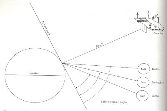
Sun – elevation correction and Earth-sun distance correction

The earth-sun distance correction is applied to normalize for the seasonal changes in the distance between the earth and the sun.

The combined effect of solar-zenith angle and earth-sun distance on the irradiance incident on the earth’s surface can be expressed as,

E = (E0 * Cos q0) / (d^2)                   where,
E = normalized solar irradiance
E0 = solar irradiance at mean earth-sun distance
q0 = sun’s angle from the zenith
d=earth-sun distance in AU [ASTRONOMICAL UNITS]


Noise removal:

  • Image noise is an unwanted disturbance in image data that is due to limitations in the sensing, signal digitization, or data recording process
  • If the difference between a given pixel value and its surrounding values exceeds an analyst-specified threshold, the pixel is assumed to contain noise.
  • The noisy pixel value can then be replaced by the average of its neighboring values.


Geometric correction
Highly systematic source of distortion involved multispectral scanning from satellite altitude is eastward rotation of the earth beneath the satellite during imaging. This causes optical sweep of the scanner to the west of the previous sweep. This is known as skew distortion. Process of deskewing involves offsetting each successive line towards the west.


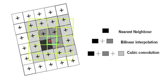
Principal of resampling using nearest neighbour, bilinear interpolation and cubic convolution.

            Nearest Neighbour

  •  Consider the green grid to be the output image to be created.
  • To determine the value of central pixel (bold), in the nearest neighbour the value of nearest original pixel is assigned, the value of black pixel in this example.
  • Value of each output pixel is assigned simply on the basis of Digital Number closest to the pixel in the input matrix.
  • Advantage of simplicity.
  • Ability to preserve original values in unaltered scene.

           Bilinear interpretation

  • Calculates the value for each output pixel based on four nearest input     pixels.
  • Weighted mean is calculated for the four nearest pixels in the original image     (dark gray and black pixels).

         
Cubic convolution

  • Each estimated value in the output matrix is found assessing values within a neighbourhood of 16 surrounding pixels (the black and all gray pixel) in the input image.

Radiometric corrections-

Radiance measured by any given system over an object is influenced by-

  • Scene illumination
  • Atmospheric conditions
  • Viewing geometry
  • Instrument response
  • Radiometric corrections can be divided into relatively simple cosmetic rectification, as well as atmospheric corrections.
  • Atmospheric corrections constitute an important step on the preprocessing of remotely sensed data. Their effect is to rescale the atmospheric raw radiance data.
  • Image data acquired under different solar illumination angles are normalized by calculating pixel brightness values assuming that sun was at zenith during each day of sensing.
  •  The correction is applied by dividing each pixel in a scene by sine of solar elevation angle for particular time and location of imaging.

              Noise Removal

Random noise or spike noise

  • Image noise is the unwanted disturbance in image data.
  • Noise removal is done before any subsequent enhancement or classification of image data.
  • The periodic line dropouts and striping are forms of random noise that may be recognized and restored by simple means. Random noise on the other hand, requires a more sophisticated restoration process such as digital filtering.
  • Random noise or temporary noise may be due to errors during transmission of data or temporary disturbance.

Individual pixels acquire DN – values that are much higher and lower than the                             surrounding pixels. In image they produce a bright and dark spot that interferes with the information extraction procedures.

  • Spike noise can be detected by mutually comparing neighbouring pixel values. If neighbouring pixel values differ by more than threshold margin, it is designated as spike noise and the DN is replaced by an interpolated DN value.

De-striping

  • One method is to compile a set of histograms for the image –one for each detector involved in a given band.
  • These histograms are then compared in terms of their mean and median values to identify problem detector.
  • A grey scale adjustment factor is applied to adjust the histograms for problem lines and others are not altered.
  • Line striping occurs due to non identical detectors response.
  • Although the detectors for all satellite sensors are carefully calibrated and matched before launch of the satellite, with time response of some detectors may drift to higher or lower levels.
  • Every scan lines are brighter or darker than the other lines. It is important to understand that valid datas are present in the defective lines, but that must be corrected to match the overall scene.


Periodic Line dropouts

  • A number of adjacent pixels along a line or an entire line may contain defective Digital Number
  • This problem is addressed by replacing defective Digital Number with the average of values for the pixels occurring in the line below and above.
  • Digital Number from the preceding line can simply be inserted in the defective pixel.


Image enhancement: Image enhancement is concerned with the modification of images to make them more suited to the capabilities of human vision. Regardless of the extent of digital intervention, visual analysis invariably plays a very strong role in all aspects of remote sensing. While the range of image enhancement techniques is broad, the following fundamental issues form the backbone of this area These procedures applied to image data in order to more effectively display or record the data for subsequent visual interpretation.

  • Contrast manipulation
  • Spatial feature manipulation
  • Multi-image manipulation

Contrast manipulation: Digital sensors have a wide range of output values to accommodate the strongly varying reflectance values that can be found in different environments. However, in any single environment, it is often the case that only a narrow range of values will occur over most areas. Grey level distributions thus tend to be very skewed. Contrast manipulation procedures are thus essential to most visual analyses.

  • Gray-level threshold is used to segment an input into two classes- one for those pixels having values below an analyst-defined gray level and one for those above this value.


•   Level slicing is where all DN’s falling within a given interval in the input image then displayed at a single  DN in the output image

•  Contrast stretching is to expand the narrow range of brightness values typically present in an input image
over a wider range of gray values.

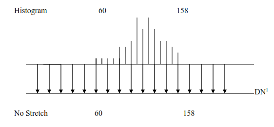
Contrast Stretching
Hypothetical sensing system whose image output levels can vary from 0-255.

Illustrates a histogram of brightness levels recorded in one spectral band over a scene.
Histogram shows scene brightness values occurring in limited range of 60-158.

Linear stretch
A more expressive display would result if we expand the range of image levels present in scene (60-158) to fill the range of display values (0-255).


  • Subtle variations in input image data values would now be displayed in the output tones that would be distinguished by the interpreter.
  • Light tonal areas would appear lighter and dark areas would appear darker.
  • Linear stretch would be applied to each pixel in an image using algorithm.


                    DN1=
DN1 = DN assigned to pixel in  output image
DN = original DN of pixel in input image
MIN=minimum value of input image to be assigned a value of 0 in the output image        (60 in example)
MAX= maximum value of input image to be assigned a value of 255 in the output image        (158 in example)

  • Each pixel’s DN is simply used to index a location in the table to find appropriate DN1 to be displayed in the output image.

Histogram – equalized stretch

  • Image values are assigned to display levels on the basis of their frequency of occurrence.
  • Image value range of 109 to 158 is now stretched over a large portion of display levels (39-255).
  • A smaller portion (0-38) is reserved for infrequently occurring image values (60-108).


Special Analysis


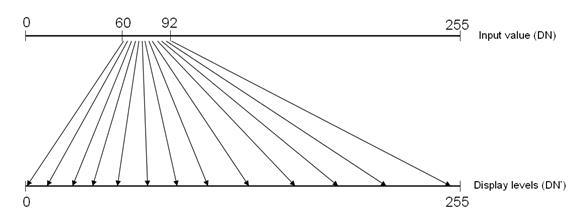
  • Specific features may be analyzed in greater radiometric detail by assigning display range exclusively to a particular range of image value.
  • If water features are represented by a narrow range of values in a scene, characteristics in water feature would be enhanced by stretching this range into small display range.
  • Output range is devoted to a small range of input values between 60 and 92.
  • On stretched display, minute tonal variations in the water range would be exaggerated.

Spatial Feature Manipulation
Spatial filtering

  • A further step in producing optimal images for interpretation is the use of filter operations.
  • Filter operations are local image transformations: a new image is calculated and the value of a pixel depends on the values of its formal neighbours.
  • Filter operations are usually carried out in single band.
  • Filters are used for spatial image enhancement, for example, to reduce noise or to sharpen blurred image.

       Convolution

  •  A moving window is established that contains an array of coefficients or weighting factors.
  • Such arrays are referred as operators or kernels and are normally an odd numbers of pixels in size.(example- 3X3, 5X5, 7X7)
  • Kernel is moved throughout original image and DN at the center of the kernel in the second (convoluted) output image is obtained by multiplying the coefficient in kernel by corresponding DN in original image and adding all the resulting products. This operation is performed for each pixel in the original image.

       
Kernel                                                                  


1/9

1/9

1/9

1/9

1/9

1/9

1/9

1/9

1/9


Original image DN

67

67

72

70

68

71

72

71

72


Convolution =  1/9(67)+1/9(67)+1/9(72)+1/9(70)+1/9(68)+1/9(71)+1/9(72)+1/9(71)+1/9(72) = 70


   70


Edge Enhancement: Directional first differencing-

  • Systematically compares each pixel in an image to one of its immediately adjacent neighbour and displays the difference in terms of gray level of output image.
  • The distance used can be horizontal, vertical or diagonal.

A

H

V

D

Horizontal first difference= DNA-DNH
Vertical first difference=DNA-DNV
Diagonal first difference=DNA-DND

  • Horizontal first difference at Pixel A would result from subtracting DN in Pixel H from Pixel A.
  • Vertical first difference would result from subtracting DN at Pixel V from that of Pixel A.
  • Diagonal first difference would result from subtracting DN at Pixel D from that of Pixel A.
  • The first differences can either be positive or negative, so a constant such as display value median (127 for 8-bit data) is added to the difference for display purpose.
  • Pixel to Pixel differences are very small, the data in enhanced image has a very narrow range. Display value median and contrast stretch must be applied to output image.


Fourier analysis

  • An image is separated into various spatial frequency components through application of mathematical operation known as Fourier transform.
  • This operation amounts to fitting a continuous function through discrete DN values if they were along each row and column in an image.
  • Peaks and valleys along any given row or column can be described mathematically by combination of sine and cosine waves with narrow amplitudes, frequencies and Phases.
  • After an image is separated into its component spatial frequency it is possible to display these values in 2D scatter Plot known as Fourier spectrum.
  • Fourier Spectrum of an image is known, it is possible to regenerate original image through application of inverse Fourier transform.This is mathematical reversal of Fourier transform.

SPATIAL FEATURE MANIPULATION

Spatial Filtering: Spatial filtering is a  “local” operation in that pixel values in an original image are modified on the basis of the gray levels of neighboring pixels. A simple low pass filter may be implemented by passing a moving window throughout an original image and creating a second image whose DN at each pixel corresponds to the local average within the moving window at each of its positions in the original image.


Composite Generation: For visual analysis, colour composites make fullest use of the capabilities of the human eye. Depending upon the graphics systems in use, composite generation ranges from simply selecting the bands to use, to more involved procedures of band combination and associated contrast stretch.

Multi-Image manipulation

Spectral Ratioing

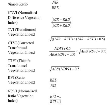
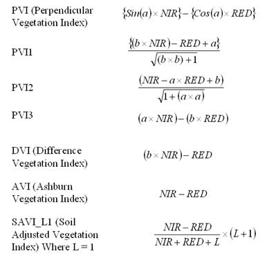
Slope based: simple arithmetic combinations that focus on the contrast between the spectral response patterns of vegetation in the Red and NIR portion of the electromagnetic spectrum.

Distance based: measures the degree of vegetation present by gauging the difference of any pixel’s reflectance from the reflectance of bare soil.

Ratio images are enhancement resulting from division of DN values in one spectral band by corresponding values in another band.

Land cover/ illumination

                               DN

Band A

Band  B

Band C

Deciduous


Sunlit

48

50

0.96

Shadow

18

19

0.95

Coniferous


Sunlit

31

45

0.69

Shadow

11

16

0.69

  • DNs observed for each cover type are lower in shadowed area than sunlit area.
  • The ratio values for each cover type are nearly identical, irrespective of illumination condition.
  • Ratioed image of scene effectively compensates for brightness variation and emphasizes colour content of the data.
  • Ratioed image are useful for discriminating spectral variations in a scene that are masked by brightness variation in images.
  • Near IR ratio for healthy vegetation is very high and for stressed vegetation it is low (as near IR reflectance decreases and red reflectance increases).
  • Thus, near IR to red (or red to near IR) ratioed image might be very useful for differentiating between area of stressed and non stressed vegetation.
  • The form and number of ratio combinations available to image analyst varies depending on the source of digital data.
  • The number of possible ratios that can be developed from n bands of data is     n(n-1). Thus, Landsat MSS data, 4(4-1), 12 different ratio combinations are possible (six original and six reciprocal).
  • The ratio TM3/TM4 is depicted so that the features such as water and roads which reflects highly in the red band (TM3) and little in IR band (TM4) are shown in lighter tones.
  • Features such as vegetation appears in darker tones because of its low reflectance in red band (TM3) and high reflectance in near IR (TM4).
  • Ratio TM5/TM2, vegetation appears in light tones because of its high reflectance in mid IR band and low reflectance in green band (TM2).
  • Ratio TM3/TM7, roads and other cultural features appear in lighter tones in this image due to high reflectance in red band (TM3) and low reflectance in mid-IR band (TM7).
  • Differences in water turbidity are readily observable in ratio image.
  • Ratio images can be used to generate false colour composites by combining three monochromatic ratio datasets.
  • Such composites have two fold advantages of combining data from more than two bands and presenting it in colour which facilitates interpretation of subtle spectral reflectance differences.
  • 20 colour combinations are possible when 6 original ratios of landsat MSS data are displayed 3 at a time.
  • 15 original ratio of non thermal ratio of non thermal TM data result in 455 different possible combinations.
  • Caution should be taken generating and interpreting ratio images.
  • Such images are intensity blind.

Hybrid colour ratio composite. (Reference:http://gimpsavvy.com/BOOK/index.html?node50.html)

  • This product is prepared by displaying two ratio images in two of the primary colours but using third of primary.
  • Noise removal is important since ratioing enhances noise pattern that are uncorrelated in component images.


Intensity-Hue-Saturation Colour Space Transformation

  • Digital images are displayed as additive colour composites using three primary colours:red,green,blue (RGB)
  • RGB colour cube is defined by brightness levels of each of the three Primary colours.
  • For display 8 bit-per-pixel data encoding, range of possible DN for each colour component 0-255.
  • 2563  possible combinations of red, green and blue DNs can be displayed by such device.
  • Every pixel is represented by 3-D coordinate Position somewhere within colour cube.
  • Line from the origin of the cube to opposite corner is gray line since DN that lies on this line has equal components of red, green and blue.
  • RGB are used in digital image processing to display normal colour, false colour IR, arbitrary colour composites.
  • Normal colour composite may be displayed by assigning TM or ETM bands 1, 2 and 3 to blue, green, red components respectively.
  • False Colour IR composite results when band 2, 3, 4 are assigned to these respective components.
  • Arbitrary colour composites When other bands or colour assignments are used.
  • Colour composite can be contrast stretched.

Intensity-hue-saturation (IHS system)
Intensity-total brightness of colour (whether it is light or dark).
Hue- dominant or average wavelength of light contributing to colour. It refers to the names we give to the colours: red, green, yellow, orange, purple, etc.
Saturation-describes a colour in terms of pale versus vivid. Purity of colour relative to gray.

Figure 4: IHS/RGB encoding and decoding for interactive image manipulation.

In this figure original RGB components are transformed into corresponding IHS components.

  • IHS components are then manipulated to enhance desired characteristics of the image.
  • These modified IHS components are transformed back to RGB system for final display.

Decorrelation stretching

  • Multiimage manipulation used when multispectral data are highly correlated.
  • Traditional contrast stretching of highly correlated data as R, G, and B displays normally only expands the range of intensities.
  • Decorrelation stretching involves exaggeration of least correlated information in an image primarily in terms of saturation with minimal change in image intensity and hue.
  • IHS transformation, decorrelation stretching is applied in a transformed image space, the results are transformed back to RGB system for final display.

CLASSIFICATION
The term pattern refers to the set of radiance measurements obtained in the various wavelength bands for each pixel.

  • Spectral pattern recognitionrefers to classification procedures that utilize this pixel-by-pixel spectral information as the basis for automated land cover classification.
  • Spatial Pattern recognition-Categorization of image pixels on the basis of their spatial relationship with the pixel surrounding them. Spatial classifier considers aspect such as – Image texture, pixel proximity, feature size, shape directionality, repetition and context.
  • Temporal Pattern recognition-uses time as an aid in feature identification. Distinct spectral and spatial changes during season can permit discrimination on multidate imagery that would be impossible given any single date.

Supervised Classification

Supervised classification - In this classification, the image analyst  “supervises” the pixel categorization process by specifying, to the computer algorithm, numerical descriptors of the various land cover types present in a scene.

  • One of the main steps in image classification is the partitioning of feature space.
  • Supervised classification requires the operator to be familiar with the area of interest.
  • The operator needs to know where to find the classes of interest in the area covered in the image.

Three basic steps are involved:

1. Training stage - the analyst identifies representative training areas and develops a numerical description  of the spectral attributes of each land cover type of interest in the scene.

2. Classification stage - each pixel in the image data set is categorized into the land cover class it most closely resembles.  The category label assigned to each pixel in this process is then recorded in the corresponding cell of an interpreted data set (an “output” image).
3. Output stage – After the entire data set has been categorized, the results are presented in the output stage.  Three typical forms of output products are thematic maps, tables of full scene or sub scène area statistics for the various land cover classes, and digital data files amenable to inclusion in a GIS.

THE CLASSIFICATION STAGE

  • Minimum-Distance-to-Means Classifier
  • Parallelepiped Classifier
  • Gaussian Maximum Likelihood Classifier


  • Each pixel in the image data set is categorized into class it closely resembles. If pixel is insufficiently similar to any training data set it is labeled as ‘unknown’.
  • Category label assigned to each pixel in this process is recorded in corresponding cell of an interpreted data (output image).
  • After entire dataset has been categorized the results are presented in output stage.


Figure 5: Spectral plot (scatter diagram) of various classes against band 2 and 3. (Reference: http://rst.gsfc.nasa.gov/Sect1/Sect1_19.html)

Minimum-Distance-to-Mean classifier.

  • First, the mean, or average, spectral value in each band for each category is determined.  These values comprise the mean vector for each category.
  • For an unknown pixel value, the distance between this pixel value and each category mean value is computed, and then the unknown pixel is assigned to the  “closest” class.

Advantage:  It is mathematically simple and computationally efficient.

Disadvantage:  It is insensitive to different degrees of variance in the spectral response data.

  • We take a sample of pixel observations from two channel digital image data set.
  • 2D digital values or measurement vectors attributed to each pixel can be expressed graphically by plotting them on scatter diagram.
  • If band 2 DN for Pixel is 10 and band 3 DN for pixel is 68, the measurement vector for pixel is represented by a point (10, 68) in the measurement space.


Figure 6: Minimum –Distance to means classifier (References: (http://www2.geog.ucl.ac.uk/~mdisney/lse/session3/mdmbox.gif)

Parallel piped classifier

  • This range may be defined by the highest and lowest digital number values in each band and appears as a rectangular area in the two-channel scatter diagram.
  • An unknown pixel is classified according to the category range, or decision region, in which it lies, or as  “unknown” if it lies outside all regions.
  • The multidimensional analogs of these rectangular areas are called parallelepipeds.
  • It is fast and efficient computationally.


Figure 7: Parallelepiped Classifier.

  • Difficulties are encountered when category range overlap. Unknown Pixel observations that occur in overlap areas will be classified as ‘not sure’.
  • Covariance is tendency of spectral values to vary similarly in two bands, resulting in elongated, slanted clouds of observation on scatter diagram.
  • In this example ‘corn’ and ‘hay’ categories have Positive covariance(slant upward towards the right) meaning that high value in Band 3 are associated with high value in band 4, low value in Band 3 are associated with low value in band 4.
  • Water category exhibits negative covariance (distribution slants down to the right) meaning that increased value of band 3 are associated with low value of band 4.
  • ‘Urban’ class shows lack of covariance, resulting in circular distribution on scatter diagram.

Gaussian maximum likelihood classifier

  • The distribution of a category response pattern can be completely described by the mean vector and covariance matrix.
  • Given these parameters, we can compute the statistical probability of a given pixel value being a member of a particular land cover class.
  • Probability density classifier is used to classify unidentified pixel by computing probability of pixel value belonging to each category.
  • Computer would  calculate probability of pixel value occurring in class ‘corn’ and likelihood of its occurring in class ‘sand’ and so on.
  • After evaluating the probability in each category, the pixel would be assigned to the most likely class (highest probability value) or labeled ‘unknown’ if probability value are below threshold set by analyst.
  • Maximum likelihood classifier delineates ellipsoidal ‘equiprobablity contours’ in scatter diagram.


Bayesian classifier

  • Analyst determines ‘a priori probability’ or anticipated likelihood of occurrence for each class in a given scene.
  • When classifying a pixel, probability of occurring ‘sand’ category might be weighted lightly and more likely ‘urban’ class weighted heavily.

Drawback

  • Large number of computations required to classify each pixel.
  • Slower computationally.

           
Graphical representation of Spectral response Patterns
Distribution of training area response patterns can be graphically displayed in many formats.
Histogram output is important when maximum likelihood classifier is used, it provides a visual check on normality of spectral response distributions.

Quantitative expressions of category separation
 A measure of statistical separation between category response patterns can be computed for all pairs of classes and can be presented in form of matrix.

Self classification of training set data-

  • Classifying training set pixels.
  • Preliminary classification is only training set models (rather than full scene) is made to determine what percentage of training set pixels are actually classified as expected.
  • These percentages are actually shown in the form of error matrix.
  • Error matrix shows how well a classifier can classify training areas.
  • Training areas are usually good, homogeneous example of each cover type can be expected to classify accurately than less pure that are found elsewhere in the scene.

Interactive Preliminary classification

  • Training data are useful in classification of full scene.
  • Preliminary classification with computationally efficient algorithm.


Representative subscene classification

  • An image analyst will perform classification of representative subset of full scene to be classified.

  
    Unsupervised Classification

  • Classes that results are spectral classes
  • Analyst must compare classified data with some form of reference data.
  • Natural spectral groupings in the data can be visually identified by plotting scatter diagram.
  • Classifier identifies distinct spectral classes present in image data.
  • There are numerous clustering algorithms that can be used to determine natural spectral groupings present in the data set.
  • Unsupervised classification is the use of algorithms that incorporate sensitivity to image ‘texture’ or ‘roughness’.
  • Texture defined by multidimensional variance observed in moving window passed through image. (3X3 window).
  • Analyst set a variance threshold below which is considered smooth homogenous and above which is considered rough heterogeneous.

Hybrid classification

  • Supervised training areas are located in regions of homogeneous cover type. Unsupervised training areas are chosen to contain numerous cover types at various locations throughout a scene.
  • Particularly valuable in analyses where there is variability in the spectral response patterns for individual cover.

Classification of mixed Pixel

  • Lower resolution sensor operating at higher altitude might focus on same field yet having its field of view occupied by mixture of soybean leaves, bare soil and grass.
  • Presents a different problem for image classification since their spectral characteristics are not representative of single land cover type.

Spectral Mixture Analysis

  • Range of techniques wherein mixed spectral signatures are compared to a set of pure reference spectra.
  • Provides useful information at sub pixel level, since multiple land cover can be detected within single pixel.

Linear mixture

  • Input to linear mixture model consists of single observed spectral signatures for each pixel in an image.
  • Pure reference spectral signatures are referred as end members because they represent cases where hundred percent of sensor’s field of view is occupied by single cover type.
  • Sum of fractional proportions of end members included in a Pixel must be equal to 1.
  • A given spectral band λ the observed DN λ for each pixel represents the sum of DNs that would be obtained from Pixel that is completely covered by a given end member weighted by fraction occupied by that member plus some unknown error.

Fuzzy classification

  • Membership grade values are assigned that describe how close a pixel measurement is to means of all measurement.

      Fuzzy Supervised classification

  • Fuzzy mean vectors and covariance matrices are developed from statistically weighted training data.
  • Instead of delineating training areas that are purely homogeneous, a combination of pure and mixed training site may be used.
  • Known mixtures of various feature types define fuzzy training class weight.
  • A classified pixel is weighted is assigned a membership grade with respect to         its membership in each information class.
  • Vegetation classification include pixel with grade 0.68 for class ‘forest’, 0.29 for ‘street’.

THE OUTPUT STAGE

  • Graphic Products
  • Tabular Data
  • Digital Information Files

Post classification smoothing

  • Classified data manifest salt and pepper due to inherent spectral variability encountered by the classifier when applied on pixel by pixel basis.
  • Application  of majority filter
  • A moving window is passed through the classified data set and majority of classes within the window is determined.
  • If centre pixel in the window is not a majority class, its identity is changed to majority class.
  • If there is no majority class in the window identity of center pixel is not changed.
  • As window progresses through the data set, original class codes are continually used not the labels as modified from previous window positions.
  • Major filters can incorporate some form of class / spatial weighting function.
  • Certain algorithms can preserve the boundaries between land cover regions and involve user –specified minimum area of any given land cover that would be maintained in the smoothed output.

Classification Accuracy Assessment
Classification error matrix

  • Compare on category by category basis, the relationship between known reference data (ground truth).
  • Such matrices are square, with number of rows and columns equal to the number of categories where classified accuracy is being assessed.
  • Several characteristics about classification performance are being expressed by error matrix.

Sample considerations

  • Test areas are area of representative, uniform land cover that is different from and considerably more extensive than training areas.
  • The accuracies obtained in these areas represent at least first approximation to classification performance through out the scene.
  • Being homogeneous test areas might not provide valid indication of classification accuracy at individual pixel level of land cover variability.

         Random sampling

  • Collections of remote data for large sample of randomly distributed points are often difficult and costly.
  • Validity of random sampling depends on ability to register reference data to image data.
  • Simple random sampling tends to under sample small but important area.
  • Stratified random sampling where each land cover category may be considered stratum is frequently used in each class.

Change detection process
Post classification comparison

  •  Two dates of imagery are independently classified and registered.
  • An algorithm can be employed to determine those pixels with a change in classification between dates.
  • Accuracy of such procedures depends upon accuracy of each of independent         classifications used in the analysis.

       Classification of multitemporal data sets

  • Single classification is performed on a combined data set for two dates of                 interest.

        Principal component analysis

  • Used to analyze multi date image composites for change detection process.
  • Two or more images are registered to from new multiband image containing all bands for each date.
  • It s often difficult to interpret and identify specific nature of changes involved.

Temporal image ratioing

  • Computing ratio of data from two dates of imaging.
  • Ratio of areas of no change tends towards 1 and areas of change will have higher or lower ratio value.

Change vector analysis

  • Change detection procedure that is conceptual extension of image differencing.

Change verses no change binary mask to guide multidate classification

  • Traditional classification of one image as reference (time 1).
  • One of the spectral bands from this date (time 2).
  • This two-band dataset is analyzed using one of the algebraic operations (example image differencing and ratioing).
  • Threshold is set to separate areas that have changed between data’s from those that have not.
  • This mask is only applied to multiband image acquired at time 2 and only areas of change are classified for time 2.

Hyper spectral Image Analysis

  • Provides vast information about physical and chemical composition of surface under observation as well as insight into characteristics of atmosphere sensor and the surface.

Disadvantage-

  • Poor signal to noise concentration
  • Increased susceptibility to effects of unwanted atmospheric interference.

Atmospheric correction of hyper spectral Images

  • The magnitude of absorption will vary from place to place and from time to time depending on concentration and particle sizes of various atmospheric constituents.
  • ‘raw’ radiance value observed by hyper spectral sensor cannot be directly compared to laboratory spectra or remotely sensed hyper spectral imagery acquired at other time or places.

Hyper image analysis techniques

  • Once a hyper spectral image has been corrected for effects of atmospheric absorption and scattering reflectance “signatures” of each pixel can be compared to previously acquired spectra for known material types.
  • Spectrum ratioing consists of dividing every reflectance value in the reference spectrum by corresponding value in image spectrum.
  • If the average deviation from 1.0 across all wavelengths falls within some small levels of tolerance, image spectrum for that pixel is considered to match the reference spectrum.

Spectral angle mapping (SAM)

  • Observed reflectance spectrum can be considered as vector in multi dimensional space, where the number of dimensions equals the number of spectral bands.
  • If the overall illumination increases or decreases the length of the vector increases or decreases but angular orientation will remain constant.

DATA MERGING AND GIS INTEGRATION
Many applications of digital image processing are enhanced through the merger of multiple data sets covering the same geographical area.

  • Multitemporal Data Merging – combining images of the same area taken on more than one date to create a product useful for visual interpretation.
  • Change Detection Procedures – involves the use of land cover change between dates of imaging.


E-mail     |     Sahyadri     |     ENVIS     |     GRASS     |     Energy     |     CES     |     CST     |     CiSTUP     |     IISc     |     E-mail