
Figure 1: Agara Bellandur Wetland
|
KORAMANGALA FLOODS: CAUSES |
| Mismanagement of Landscape: Abuse of Bellandur-Agara wetlands, Narrowing and Concretising RajaKaluve and encroachment of storm water drains, Dumping of solid waste & building debris, Apathy of Civic Agencies |
| T.V. Ramachandra Vinay S Bharath H. Aithal |
|
|
Violation that persist in Bellandur – Agara wetland (Figure 1) are:
Belladur Agara wetland is the pristine ecosystem supporting dependent biota and was aiding as a zone for the inundation of floodwater, percolation of precipitation, sustained recharge of ground water resources, while reducing overland flow. The wetlands are part of flood plains that follows the terrain. Consequences of continued abuse of wetlands are (i) increased instances of flooding, (ii) enhanced velocities of the discharge (iii) reduced recharge of ground water, (iv) loss of life and damages to the property.
Bellandur-Agara wetland’s integrity is altered due to (i) filling of low lying area with construction debris, (ii) removal of interconnecting drains (visible in remote sensing data of 2000, Figure 2) , (iii) narrowing and concretizing drains to aid the encroachment. Figure 1 indicates the Revenue map of Agara village indicating Wetland under study. Cyan line in the revenue map indicates channels connecting Agara and Bellandur lakes along the wetland
Figure 1: Agara Bellandur Wetland
Land cover dynamics in the wetland of Agara Bellandur lake is as presented in Figure 2. It is observed that since 2002, construction debris, soil were constantly dumped in the wetland, altering the topography (undulating terrains are levelled). The wetland was completely altered in 2012 with the disappearance of connecting drains due to large scale filling, excavations for construction activity. Now, only drains in the army campus exists.


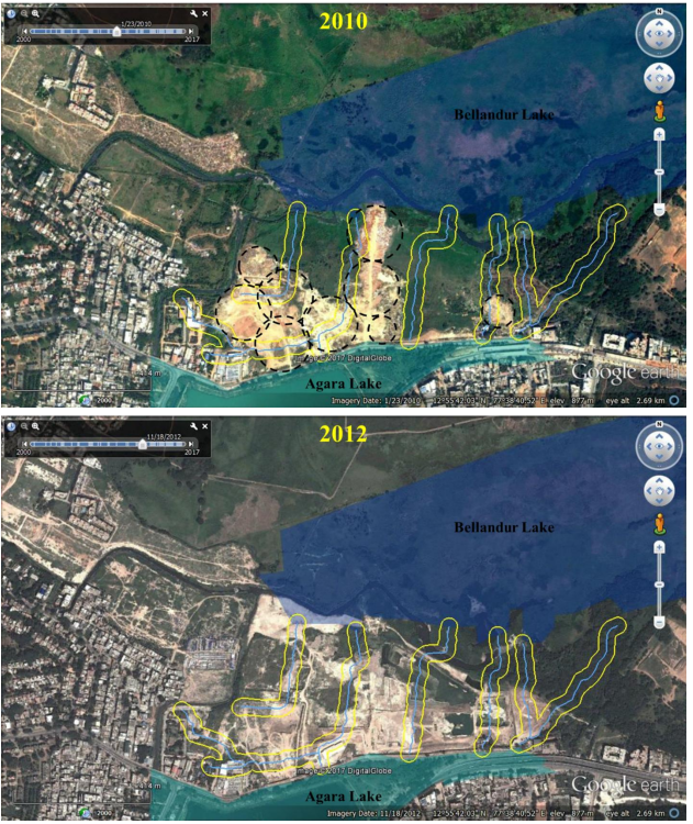


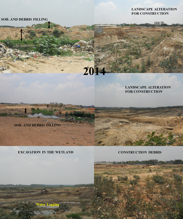
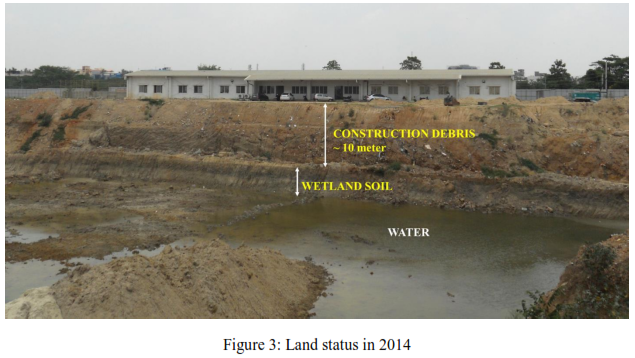
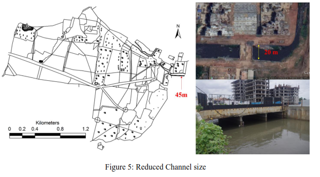
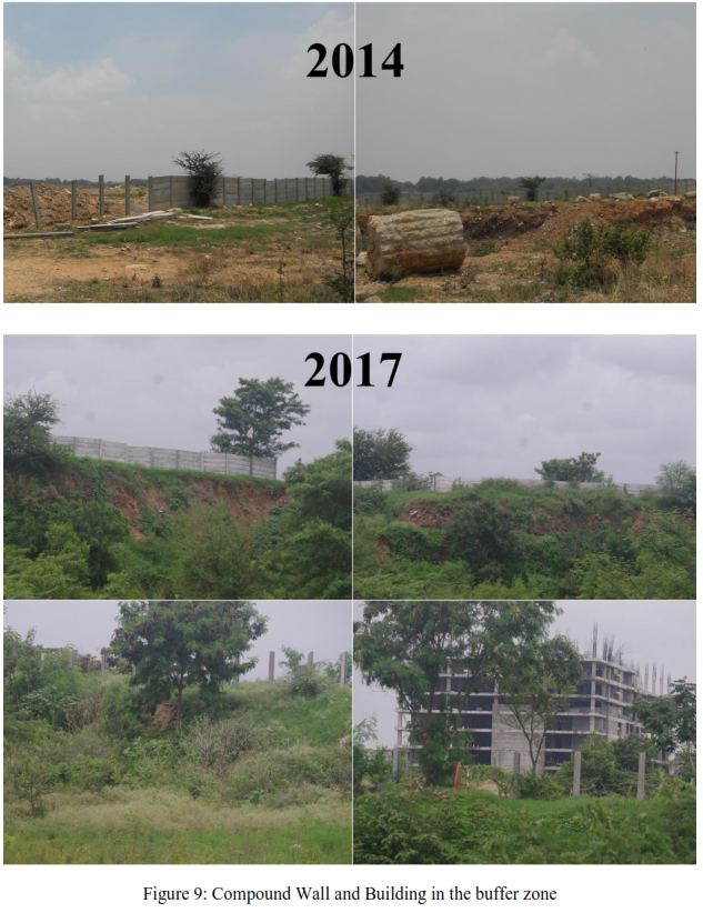
Figure 3 and Figure 4 demonstrates the alterations in the wetlands region observed at the site at sites in 2014 and 2017 field visits. Large scale construction debris, Soil and Solid waste filled, over which construction activity was under progress. Figure 4 also depicts the concretized channel and violation of norms. The channel has been reduced in width from 45 m to nearly 20 m (Figure 5).
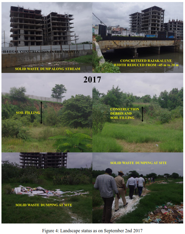
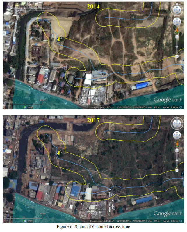
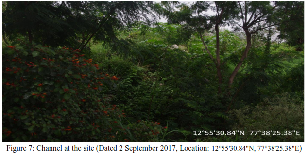
Causal Factor 2: Debris in storm water drains: Figure 6 indicates the status of one of the connecting channel during the field visit on 1st September 2017. The channel continued to be filled with construction debris (since 2004). Figure 7 depicts the current status of one of the connecting channel.


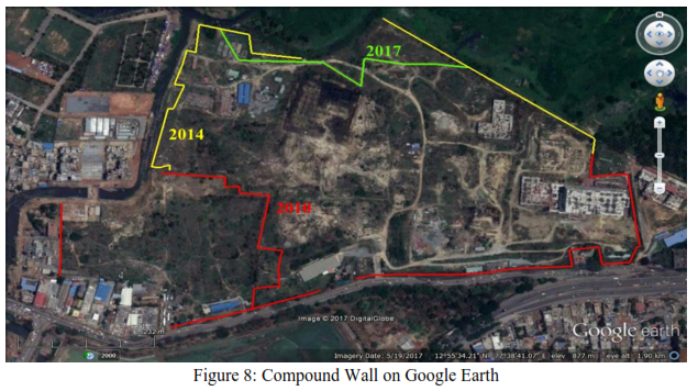
Causal Factor 3 – Erection of compound wall: The compound walls were erected in the wetlands region, hindering flow of water. These structures violating the hydrologic regime as (i) the compound walls inside wetlands restrict the movement of water from upstream to downstream, (ii) compound wall is being built (after filling and altering the topography) altering the wetlands physical integrity. Figure 8 depicts the Compound walls on Google earth. Figure 9 depicts the status of compound walls in 2014 and 2017. IT can be observed that a new boundary has been erected in 2017, but the land is seeming not be rejuvenated to the original status.
Causal Factor 4: Narrowing and Concretisation of storm water drains
During the field work on 1 May 2017 along with CEO, KLCDA it was observed
Figure 10 shows revenue map of Jakkasandra village which is in the upstream of Bellanduru lake. Figure 11 illustrates narrowed width of rajakaulve between 1908 and 2017. It can be noted that nearly 50% of the channel width is reduced and has been concretized.
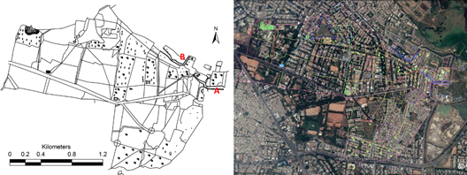
Figure 1:Jakkasandra Village map
(Note : A indicates the Rajakaluveys measured for change in width)
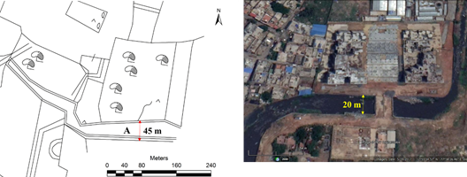
Figure 11: Rajakaluve A: from Agara Lake to Bellandur Lake
Need to move away from contractor with consultant driven design to maximise individual gains (through cement concretization etc.) -Estimate of Rs 8 crore per kilometer of drain is too exorbitant and waste of public money.
Open Channels Flow: Flow of fluids in natural or manmade channels whose surface is exposed to the atmosphere and flow is due to gravitational force are referred to as open channel flow. In order to understand the channels capabilities or designing the channels, Manning’s equation is generally used. Mannings equation is a function of channels physical properties such as wetted perimeter, cross sectional area, bed slope, bed material, depth of flow, etc.
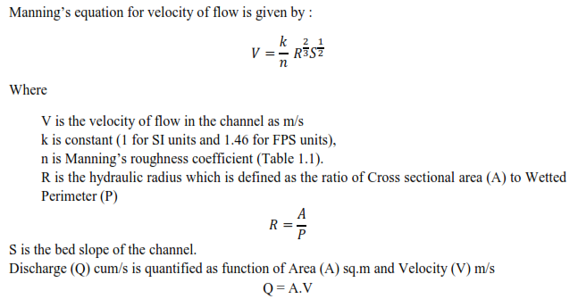
Table 1.1: Manning’s Roughness coefficient (n)
Type of Channel and Description |
Minimum |
Normal |
Maximum |
Natural streams - minor streams (top width at flood stage < 100 ft) |
|||
1. Main Channels |
|
|
|
a. clean, straight, full stage, no rifts or deep pools |
0.025 |
0.030 |
0.033 |
b. same as above, but more stones and weeds |
0.030 |
0.035 |
0.040 |
c. clean, winding, some pools and shoals |
0.033 |
0.040 |
0.045 |
d. same as above, but some weeds and stones |
0.035 |
0.045 |
0.050 |
e. same as above, lower stages, more ineffective |
0.040 |
0.048 |
0.055 |
f. same as "d" with more stones |
0.045 |
0.050 |
0.060 |
g. sluggish reaches, weedy, deep pools |
0.050 |
0.070 |
0.080 |
h. very weedy reaches, deep pools, or floodways |
0.075 |
0.100 |
0.150 |
2. Mountain streams, no vegetation in channel, banks usually steep, trees and brush along banks submerged at high stages |
|||
a. bottom: gravels, cobbles, and few boulders |
0.030 |
0.040 |
0.050 |
b. bottom: cobbles with large boulders |
0.040 |
0.050 |
0.070 |
3. Floodplains |
|
|
|
a. Pasture, no brush |
|
|
|
1.short grass |
0.025 |
0.030 |
0.035 |
2. high grass |
0.030 |
0.035 |
0.050 |
b. Cultivated areas |
|
|
|
1. no crop |
0.020 |
0.030 |
0.040 |
2. mature row crops |
0.025 |
0.035 |
0.045 |
3. mature field crops |
0.030 |
0.040 |
0.050 |
c. Brush |
|
|
|
1. scattered brush, heavy weeds |
0.035 |
0.050 |
0.070 |
2. light brush and trees, in winter |
0.035 |
0.050 |
0.060 |
3. light brush and trees, in summer |
0.040 |
0.060 |
0.080 |
4. medium to dense brush, in winter |
0.045 |
0.070 |
0.110 |
5. medium to dense brush, in summer |
0.070 |
0.100 |
0.160 |
d. Trees |
|
|
|
1. dense willows, summer, straight |
0.110 |
0.150 |
0.200 |
2. cleared land with tree stumps, no sprouts |
0.030 |
0.040 |
0.050 |
3. same as above, but with heavy growth of sprouts |
0.050 |
0.060 |
0.080 |
4. heavy stand of timber, a few down trees, little |
0.080 |
0.100 |
0.120 |
5. same as 4. with flood stage reaching branches |
0.100 |
0.120 |
0.160 |
4. Excavated or Dredged Channels |
|
|
|
a. Earth, straight, and uniform |
|
|
|
1. clean, recently completed |
0.016 |
0.018 |
0.020 |
2. clean, after weathering |
0.018 |
0.022 |
0.025 |
3. gravel, uniform section, clean |
0.022 |
0.025 |
0.030 |
4. with short grass, few weeds |
0.022 |
0.027 |
0.033 |
b. Earth winding and sluggish |
|
|
|
1. no vegetation |
0.023 |
0.025 |
0.030 |
2. grass, some weeds |
0.025 |
0.030 |
0.033 |
3. dense weeds or aquatic plants in deep channels |
0.030 |
0.035 |
0.040 |
4. earth bottom and rubble sides |
0.028 |
0.030 |
0.035 |
5. stony bottom and weedy banks |
0.025 |
0.035 |
0.040 |
6. cobble bottom and clean sides |
0.030 |
0.040 |
0.050 |
c. Dragline-excavated or dredged |
|
|
|
1. no vegetation |
0.025 |
0.028 |
0.033 |
2. light brush on banks |
0.035 |
0.050 |
0.060 |
d. Rock cuts |
|
|
|
1. smooth and uniform |
0.025 |
0.035 |
0.040 |
2. jagged and irregular |
0.035 |
0.040 |
0.050 |
||||
e. Channels not maintained, weeds and brush uncut |
|
|
|
||||
1. dense weeds, high as flow depth |
0.050 |
0.080 |
0.120 |
||||
2. clean bottom, brush on sides |
0.040 |
0.050 |
0.080 |
||||
3. same as above, highest stage of flow |
0.045 |
0.070 |
0.110 |
||||
4. dense brush, high stage |
0.080 |
0.100 |
0.140 |
||||
5. Lined or Constructed Channels |
|
|
|
||||
a. Cement |
|
|
|
||||
1. neat surface |
0.010 |
0.011 |
0.013 |
||||
2. mortar |
0.011 |
0.013 |
0.015 |
||||
b. Wood |
|
|
|
||||
1. planed, untreated |
0.010 |
0.012 |
0.014 |
||||
2. planed, creosoted |
0.011 |
0.012 |
0.015 |
||||
3. unplaned |
0.011 |
0.013 |
0.015 |
||||
4. plank with battens |
0.012 |
0.015 |
0.018 |
||||
5. lined with roofing paper |
0.010 |
0.014 |
0.017 |
||||
c. Concrete |
|
|
|
||||
1. trowel finish |
0.011 |
0.013 |
0.015 |
||||
2. float finish |
0.013 |
0.015 |
0.016 |
||||
3. finished, with gravel on bottom |
0.015 |
0.017 |
0.020 |
||||
4. unfinished |
0.014 |
0.017 |
0.020 |
||||
5. gunite, good section |
0.016 |
0.019 |
0.023 |
||||
6. gunite, wavy section |
0.018 |
0.022 |
0.025 |
||||
7. on good excavated rock |
0.017 |
0.020 |
|
||||
8. on irregular excavated rock |
0.022 |
0.027 |
|
||||
d. Concrete bottom float finish with sides of: |
|
|
|
||||
1. dressed stone in mortar |
0.015 |
0.017 |
0.020 |
||||
2. random stone in mortar |
0.017 |
0.020 |
0.024 |
||||
3. cement rubble masonry, plastered |
0.016 |
0.020 |
0.024 |
||||
4. cement rubble masonry |
0.020 |
0.025 |
0.030 |
||||
5. dry rubble or riprap |
0.020 |
0.030 |
0.035 |
||||
e. Gravel bottom with sides of: |
|
|
|
||||
1. formed concrete |
0.017 |
0.020 |
0.025 |
||||
2. random stone mortar |
0.020 |
0.023 |
0.026 |
||||
3. dry rubble or riprap |
0.023 |
0.033 |
0.036 |
||||
f. Brick |
|
|
|
||||
1. glazed |
0.011 |
0.013 |
0.015 |
||||
2. in cement mortar |
0.012 |
0.015 |
0.018 |
||||
g. Masonry |
|
|
|
||||
1. cemented rubble |
0.017 |
0.025 |
0.030 |
||||
2. dry rubble |
0.023 |
0.032 |
0.035 |
||||
h. Dressed ashlar/stone paving |
0.013 |
0.015 |
0.017 |
||||
i. Asphalt |
|
|
|
||||
1. smooth |
0.013 |
0.013 |
|
||||
2. rough |
0.016 |
0.016 |
|
||||
j. Vegetal lining |
0.030 |
|
0.500 |
||||
Manning's n for Closed Conduits Flowing Partly Full (Chow, 1959). |
|||||||
Type of Conduit and Description |
Minimum |
Normal |
Maximum |
|
|||
1. Brass, smooth: |
0.009 |
0.010 |
0.013 |
|
|||
2. Steel: |
|
|
|
|
|||
Lockbar and welded |
0.010 |
0.012 |
0.014 |
|
|||
Riveted and spiral |
0.013 |
0.016 |
0.017 |
|
|||
3. Cast Iron: |
|
|
|
|
|||
Coated |
0.010 |
0.013 |
0.014 |
|
|||
Uncoated |
0.011 |
0.014 |
0.016 |
|
|||
4. Wrought Iron: |
|
|
|
|
|||
Black |
0.012 |
0.014 |
0.015 |
|
|||
Galvanized |
0.013 |
0.016 |
0.017 |
|
|||
5. Corrugated Metal: |
|
|
|
|
|||
Subdrain |
0.017 |
0.019 |
0.021 |
|
|||
Stormdrain |
0.021 |
0.024 |
0.030 |
|
|||
6. Cement: |
|
|
|
|
|||
Neat Surface |
0.010 |
0.011 |
0.013 |
|
|||
Mortar |
0.011 |
0.013 |
0.015 |
|
|||
7. Concrete: |
|
|
|
|
|||
Culvert, straight and free of debris |
0.010 |
0.011 |
0.013 |
|
|||
Culvert with bends, connections, and some debris |
0.011 |
0.013 |
0.014 |
|
|||
Finished |
0.011 |
0.012 |
0.014 |
|
|||
Sewer with manholes, inlet, etc., straight |
0.013 |
0.015 |
0.017 |
|
|||
Unfinished, steel form |
0.012 |
0.013 |
0.014 |
|
|||
Unfinished, smooth wood form |
0.012 |
0.014 |
0.016 |
|
|||
Unfinished, rough wood form |
0.015 |
0.017 |
0.020 |
|
|||
8. Wood: |
|
|
|
|
|||
Stave |
0.010 |
0.012 |
0.014 |
|
|||
Laminated, treated |
0.015 |
0.017 |
0.020 |
|
|||
9. Clay: |
|
|
|
|
|||
Common drainage tile |
0.011 |
0.013 |
0.017 |
|
|||
Vitrified sewer |
0.011 |
0.014 |
0.017 |
|
|||
Vitrified sewer with manholes, inlet, etc. |
0.013 |
0.015 |
0.017 |
|
|||
Vitrified Subdrain with open joint |
0.014 |
0.016 |
0.018 |
|
|||
10. Brickwork: |
|
|
|
|
|||
Glazed |
0.011 |
0.013 |
0.015 |
|
|||
Lined with cement mortar |
0.012 |
0.015 |
0.017 |
|
|||
Sanitary sewers coated with sewage slime with bends and connections |
0.012 |
0.013 |
0.016 |
|
|||
Paved invert, sewer, smooth bottom |
0.016 |
0.019 |
0.020 |
|
|||
Rubble masonry, cemented |
0.018 |
0.025 |
0.030 |
|
|||
Manning's n for Corrugated Metal Pipe (AISI, 1980). |
|
||||||
Type of Pipe, Diameter and Corrugation Dimension |
n |
|
|||||
1. Annular 2.67 x 1/2 inch (all diameters) |
0.024 |
|
|||||
2. Helical 1.50 x 1/4 inch |
|
|
|||||
8" diameter |
0.012 |
10" diameter |
0.014 |
3. Helical 2.67 x 1/2 inch |
|
12" diameter |
0.011 |
18" diameter |
0.014 |
24" diameter |
0.016 |
36" diameter |
0.019 |
48" diameter |
0.020 |
60" diameter |
0.021 |
4. Annular 3x1 inch (all diameters) |
0.027 |
5. Helical 3x1 inch |
|
48" diameter |
0.023 |
54" diameter |
0.023 |
60" diameter |
0.024 |
66" diameter |
0.025 |
72" diameter |
0.026 |
78" diameter and larger |
0.027 |
6. Corrugations 6x2 inches |
|
60" diameter |
0.033 |
72" diameter |
0.032 |
120" diameter |
0.030 |
180" diameter |
0.028 |
Source: www.fsl.orst.edu/geowater/FX3/help/8_Hydraulic_Reference/Mannings_n_Tables.htm
DESIGN – ILLUSRATION OF NATURAL DRAINS SUPREMACY
Highest rainfall in a day was observed to be 109 mm in the year 2013 (as recorded between 31st May 2013 8:30 AM and 1st June 2013 8:30 AM), w.r.t which an yield of 1022 kilo.cum of water is generated. Considering that the rainfall has occurred within 6 hours, Discharge would be about 47.31 cum/s. Open channels along the valley zones should be able to carry the discharge of 47.31 cum/s, without clogging or surpassing the flood plain.
In order to quantify the discharge along the channel, various scenarios were observed, i.e., current width of which is about 7 to 8 meters in width, and width as per cadastral maps along with various bed characteristics such as concrete bed, soil bed and bed with vegetation., details are as presented in table 1.2.
The analysis of Channels shows that in the current scenario, where the channel width is about 7 – 8 meters in width, has a capacity to carry discharge of 51.47 cum/s at minimum roughness coefficient of 0.40 for channels with presence of weeds/reeds and stones along the beds indicating that the channels would easily cater to the exiting discharge of 47.31 cum/s.
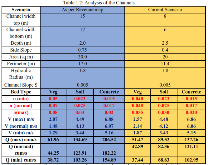
Velocity estimates indicate that presence of vegetation along with other bed materials (Soil, stones) would help in reducing velocity of flow. In the existing scenario, flow velocity was estimated to be 1.87 to 2.57 m/s, compared to soil bed or concrete bed which has lower friction where the velocity ranges were between 3.43 to 6.86 m/s.
If the drainages were reclaimed as per the cadastral maps, the width of the channel would be around 15 to 18 meters, considering maximum flow depth as 2 meters, channel with natural vegetation (reeds and weeds) would have low flow velocities between 1.29 to 2.07 m/s which is much lower as against the current scenario, and with discharges upto 61.96cum/s, indicating that the valley in its natural condition had a higher sewage carrying potential even with lower depth of flow.
Studies showing relation between Bed material and Surface flows: Studies carried by Nepf in 2012, Miyab et al 2014, Miyab et al 2015, Morri et al 2016, Jarvella, 2002, Green 2005, highlights the role of vegetation on the river channels:
Solutions:
Reference
Nepf, Heidi M., 2012, Hydrodynamics of Vegetated Channels. Journal of Hydraulic Research 50(3) pp: 262-279.
Miyab, N. M., Afzalimehr, H., Singh, V. P., 2015, Experimental Investigation of Influence of Vegetation on Flow Turbulence, International Journal of Hydraulic Engineering, 4(3), pp: 54 – 69, DOI: 10.5923/j.ijhe.20150403.02
Miyab, N. M., Afzalimehr, H., Singh, V. P., Ghorbani, B., 2014, On Flow Resistance Due to Vegetation in a Gravel-Bed River, International Journal of Hydraulic Engineering, 3(3), pp: 54 – 69, DOI: 10.5923/j.ijhe.20140303.02
Morrie, M., Soulamia, A., Belleudy, P., 2016, Mean Velocity Predictions in Vegetated Flows, Journal of Applied Fluid Mechanics, 9(3), pp: 1273-1283
Marjoribanks, T. I., Hardy, R. J., Lane, S. N., Tancock, M. J., 2017, Patch-scale representation of vegetation within hydraulic models, Earth Surface Processes and Landforms, 42, pp: 699 – 710, DOI: 10.1002/esp.4015
Jarvela, J., 2002., Flow resistance of flexible and stiff vegetation: a flume, study with natural plants. Journal of Hydrology, 269: 44–54.
Green, J. C. 2005. Modelling flow resistance in vegetated streams: review and development of new theory. Hydrological Processes 19: 1245–1259
CAUSAL FACTOR 5: LOSS OF INTERCONNECTIVITY AMONG LAKES
The undulating terrain (varying from about 700 m to about 962 m AMSL) in the region aided in the formation of interconnected lakes in the region (Figure 2.2). Bangalore City was once aptly known as ‘city of lakes’ due to the presence of large number of lake (about 285 lakes in an area of 161 sq km, Spatial extent of Bangalore in 1980’s). These lakes were all interconnected with canals / drains (kaluveys’s) to enable transferring excess water to the next lake. These lakes catered the basic needs such as maintaining and recharging ground water, drinking water to the surrounding people, habitat for fishes and other aquatic ecosystems, sustaining food (fish, etc.) and agricultural activities, etc.
The drainage network in Bangalore carries water to the River Cauvery through its tributaries Arkavathi, Pinakini or Pennar and Shimsha. The central, northern and eastern portion is undulating with the upland tracts occupied by scrubs, while the low lands occupied by series of tanks formed by embanking the streams along the valley. These valleys consists of varying size water bodies from small ponds to large lakes. The southern portion of the land consists of hills that are close together and are surrounded by thick jungles.
Bangalore being located on the ridge, forms three watersheds as precipitation flows as runoff in three directions along the valleys (Figure 2.2) - Koramangala Challaghatta Valley (K&C Valley), Hebbal Valley (H Valley) and the Vrishabhavati Valley (V Valley). Under the administrative boundary of Bruhat Bengaluru, K&C valley is the largest encompassing an area of 255 square kilometers, followed by Hebbal valley with an area of 207 square kilometers and Vrishabhavati valley with an area of 165 square kilometers. Both K&C valley and Hebbal valley joins at Nagondanahalli village (BBMP Ward 94 – Hagadur) which further flow to Dakshina Pinakini River, where as Vrishabhavati valley joins Arkavathi river which is a tributary of river Cauvery.
During 1800, there were 1452 water bodies with the storage capacity of 35 TMC (in the current spatial extent of 741 sq.km.). The number of lakes in Bangalore has reduced from nearly 285 (spatial extent of Bangalore: 161 sq.km. in early seventies) to 194 (spatial extent of Bangalore: 741 sq.km. in 2006). Unplanned rapid urbanisation during late nineties, witnessed large-scale unrealistic, uncontrolled developmental activities in the neighborhood of lakes, which led to
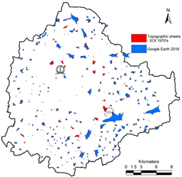
During the last four decades there has been 79% reduction in water bodies and the number of lakes in Bangalore is given in Figure 12. Loss of interconnectivity is evident in Figure 13 due to encroachments.
 |
|
Figure 12: Status of Lake in Bangalore |
Figure 13: Loss of interconnectivity among lakes |
