|
|
ENVIS Technical Report 124, October 2017 |
CONSTRUCTED WETLANDS FOR TERTIARY TREATMENT OF WASTEWATER |
Constructed wetlands (CW’s) are efficient wastewater treatment systems consisting of shallow (usually less than 1 m deep) ponds or channels which have been planted with aquatic plants, and which rely upon natural microbial, biological, physical and chemical processes to treat wastewater (EPA, 2000; Vymazal, 2007). Wastewater treatment using through engineered wetlands (constructed wetlands: CW) has emerged as a sustainable, environmentally friendly solution in many countries across the world (Kadlec and Wallace, 2009), due to the ability of CW’s to recycle, transfer and/or immobilize a wide range of potential contaminants (Greenway and Wolley, 1999). Indeed, besides domestic and municipal application, the use of constructed wetlands has wide applications including treatment of industrial effluent, special wastewater (e.g. from hospitals, acid mine drainage), agricultural effluent, landfill leachate, road runoff and sludge consolidation (Vymazal, 1998). Compared to high-cost conventional mechanical treatment systems, constructed wetland technology is economical, easy operation and maintenance. Moreover, minimal fossil-fuel is required; and without any chemical energy (Kadlec and Knight, 1996). The use of low cost option for water purification is particularly valuable and exploitable for the protection of water quality in aquatic ecosystem catchments in developing countries (Denny, 1997).
1.1 CLASSIFICATION OF CONSTRUCTED WETLANDS [Wu et al., 2015; Zhang et al., 2015]: CW’s are broadly categorised as Sub-surface flow constructed wetland (SSFCW) and Free surface flow constructed wetland (FSFCW).
- FSFCW: Free surface flow constructed wetland
- SSFCW: Subsurface flow constructed wetland
- HFSSCW: Horizontal flow Subsurface constructed wetland.
- VFSSCW: Vertical flow Subsurface constructed wetland.
- FSFCW: Free surface flow constructed wetland consist of basins or channels, with soil or another suitable medium to support the rooted vegetation (if present) and water at a relatively shallow depth flowing through the unit (figure 1.1). The shallow water depth (0.3-0.6 m), low flow velocity, and presence of the plant stalks and litter regulate water flow and, especially in long, narrow channels, ensure plug-flow conditions (EPA, 1999; Reed et al., 1988). The major removal mechanisms for suspended solids are sedimentation, filtration, aggregation and surface adhesion (Zhang et al., 2015).In heavily loaded FWS wetlands, the anoxic zone can move quite close to the water surface. Biomass decay provides a carbon source for denitrification, but the same decay competes with nitrification for oxygen supply. Low winter temperature enhances oxygen solubility in water, but slow microbial activity (Kadlec and Knight, 1996). The decomposition pathway by which wetland carbon loads are processed is determined by a balance between the carbon load and the supply of oxygen. Oxygen is supplied to the wetland water column by diffusion through the air-water interface and via the photosynthetic activity of plants in the water column, namely periphyton and algae (Kadlec et al., 2000). Nitrogen is most effectively removed in FWS constructed wetlands by nitrification/denitrification. In FWSCW’s, plant uptake is considered as the primary mechanism for reducing nitrogen (Vymazal, 2007).
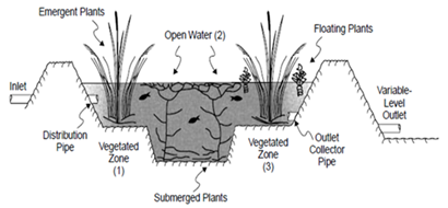
Figure 1.1: FSFCW (adapted from EPA, 2000)
1.1.2 HFSSCW: In horizontal sub-surface flow constructed wetland, the wastewater is fed in at the inlet and flows slowly through the porous medium under the surface of the bed in a more or less horizontal path (figure 1.2) until it reaches the outlet zone where it is collected before leaving via level control arrangement at the outlet (UN-HABITAT, 2008). During the passage the wastewater will come in contact with a network of aerobic, anoxic and anaerobic zones. The aerobic zones occur around roots and rhizomes that leak oxygen into the substrate (Cooper et al., 1996).One of the primary removal/retention mechanisms for suspended solids in HFCW’s is the flocculation and settling of colloidal and supra-colloidal particulates. Other effective removal mechanisms in HF systems are gravity sedimentation, straining and physical capture and adsorption on biomass film attached to gravel and root systems (Zhang et al., 2015). Phosphorus is removed by sorption and precipitation. HSSFCW’s have an even higher potential for phosphorus removal as the substrate is constantly flooded and there is little fluctuation in redox potential in the bed (Vymazal, 2007). Nitrogen is removed in HFCW’s primarily by nitrification/denitrification.
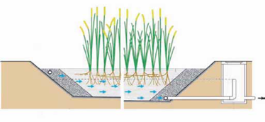
Figure 1.2: HFSSCW (adapted from UN-HABITAT, 2008)
VFSSCW: Vertical flow (VF) constructed wetlands comprise a flat bed of graded gravel topped with sand planted with macrophytes (figure 1.3). VFCW’s are fed intermittently with a large batch thus flooding the surface. Wastewater then gradually percolates down through the bed and is collected by a drainage network at the base. The bed drains completely free and it allows air to refill the bed (UN-HABITAT, 2008). This kind of dosing leads to good oxygen transfer and hence the ability to nitrify (Cooper et al., 1996).The major role of macrophytes in VFCW’s is to help maintain the hydraulic conductivity of the bed. Moreover, the second generation VFSSCW has been developed with only a single bed (Arias and Brix, 2005) that helps in rapid uptake and nitrification. Literatures reveal, removal efficiencies for TN in VSSFCW’s to be slightly higher (p > 0.05; 53.32%) than those in HSSFCW’s (50.03%).In contrast, phosphorus is removed primarily by ligand exchange reactions, whereby phosphate displaces water or hydroxyls from the surface of Fe and Al hydrous oxides (Faulkner and Richardson, 1989).For both HF and VF systems emergent macrophytes like Typha and Phragmites are commonly used as vegetation.
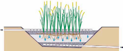
Figure 1.3: VFSSCW (adapted from UN-HABITAT, 2008)
Species selection- For wastewater treatment, macrophytes selected for planting should;
- be active vegetative colonizers with spreading rhizome systems,
- have considerable biomass or stem densities to achieve maximum velocity gradient and enhanced flocculation and sedimentation, and
- be a combination of species that will provide coverage over the broadest range of water depths encountered.
Planting techniques:
- Plants can be introduced to a wetland by transplanting roots, rhizomes, tubers, seedling or mature plants;
- by importing substrate and seed bank from nearby wetlands or;
- by relying completely on seed bank of the original site;
- choosing plants from wild stock is more desirable than nurseries as they are better adapted to environmental conditions in constructed wetlands;
- plants collected from nearby area must be planted within 36 hrs. If nursery plants are used, they should be from similar climatic conditions & should be shipped rapidly to minimize losses;
- if seed are used, they should be evaluated for the species present and their viability.
The macrophyte planting density can be as close as 0.3 m (1ft) centre or as much as 1 m (3ft). The higher the density, the more rapid will be the development of a mature and completely functional wetland system. However, high density plantings will increase construction costs significantly. FWS wetlands should be planted more densely owing to the role of the plants in the treatment process, whereas subsurface systems can be planted less densely.
If mechanical equipment is used for planting, the unplanted areas should be kept dry until planting is complete. Since the bottom is sloped toward the discharge end, planting should start at the outlet and proceed toward the inlet. Sprinklers and shallow flooding have been used to keep the planted areas wet. If the FWS wetland is designed to treat a high-strength influent such as primary treated wastewater, a cleaner water source or diluting the wastewater with storm water or well water is recommended for the initial planting and growth period so the plants are not overly stressed.
In subsurface systems, it is typical practice to flood the wetland cell to the surface of the media prior to planting and to maintain that level until significant growth has occurred. Later, the water level is lowered to the intended operating level. A layer of straw or hay mulch 15 to 20 cm (6–8 in) in thickness should be placed on the gravel surface to protect the new plants from the high summer surface temperatures that can occur on bare gravel surfaces. The mulch also is useful for providing thermal insulation during the first winter of operation in northern climates.
1.2. AREA REQUIRED FOR CONSTRUCTED WETLANDS
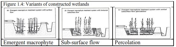
Taking advantage of remediation capability of aquatic plants (emergent macrophytes, free floating macrophytes) and algae, constructed wetlands have been designed and implemented successfully for efficient removal of nutrients (N, P, heavy metals, etc.). Different types of constructed wetlands (sub surface 0.6 m depth, surface: 0.4 m, could be either horizontal or vertical) are given in Figure 1.4. Area required for constructed wetlands depends on the influent sewage quality and expected treatment (BOD removal, etc) is given in equation 1 (Vymazal et.al, 1998). Estimates show that to treat 1 MLD influent, area required is about 1.7 hectares. Figure 1.5 gives the proposed design of wetlands to treat 1 MLD.
A = Qd(lnCo – lnCt) / KBOD
Where, A = area; Qd= ave flow (m3/day); Co & Ct = influent & effluent BOD (mg/L); KBOD = 0.10
For example to treat influent (raw sewage: BOD: 60-80) and anticipated effluent (with BOD 10), area required is about 1.7 to 2 hectares.
Figure 1.5: Conceptual design of wetlands
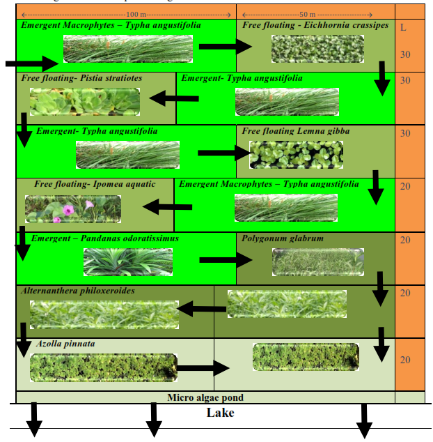
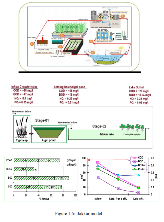
1.3 INTEGRATED WETLAND SYSTEM-JAKKUR MODEL
Integrated wetlands system consists of sewage treatment plant (STP), constructed wetlands (with location specific macrophytes) and algal pond integrated with a lake (Figure 1.6). Constructed wetland aid in water purification (nutrient, heavy metal and xenobiotics removal) and flood control through physical, chemical, and biological processes. When sewage is released into an environment containing macrophytes and algae a series of actions takes place. Through contact with biofilms, plant roots and rhizomes processes like nitrification, ammonification and plant uptake will decrease the nutrient level (nitrate and phosphates) in wastewater. Algae based lagoons treat wastewater by natural oxidative processes. Various zones in lagoons function equivalent to cascaded anaerobic lagoon, facultative aerated lagoons followed by maturation ponds. Microbes aid in the removal of nutrients and are influenced by wind, sunlight and other factors (Ramachandra et al., 2014). This model is working satisfactorily at Jakkur. The sewage treatment plant removes contaminants (evident from lower COD and BOD) and mineralises organic nutrients (NO3-N, PO43- P to inorganic constituents. Integration of the conventional treatment system with wetlands [consisting of reed bed (with typha etc.) and algal pond] would help in the complete removal of nutrients in the cost effective way. Four to five days of residence time in the lake helps in the removal of pathogen apart from nutrients. However, this requires regular maintenance through harvesting macrophytes and algae (from algal ponds). Harvested algae would have energy value, which could be used for biofuel production. The combined activity of algae and macrophytes helps in the removal of ~45% COD, ~66 % BOD, ~33 % NO3-N and ~40 % PO43-P. Jakkur lake acts as the final level of treatment that removes ~32 % COD, ~23% BOD, ~ 0.3 % NO3-N and ~34 % PO43-P. The lake water with a nominal effort of sunlight exposure and filtration would provide potable water. Replication of this model in rapidly urbanizing landscapes (such as Bangalore, Delhi, etc.) would help in meeting the water demand and also mitigating water scarcity through recharging of groundwater sources with remediation.
|
Dr. T.V. Ramachandra
Centre for Sustainable Technologies, Centre for infrastructure, Sustainable Transportation and Urban Planning (CiSTUP), Energy & Wetlands Research Group, Centre for Ecological Sciences, Indian Institute of Science, Bangalore – 560 012, INDIA.
E-mail : tvr@iisc.ac.in
Tel: 91-080-22933099/23600985,
Fax: 91-080-23601428/23600085
Web: http://ces.iisc.ac.in/energy
Sudarshan P. Bhat Energy & Wetlands Research Group, Centre for Ecological Sciences, Indian Institute of Science, Bangalore – 560 012, INDIA.
E-mail: sudarshanb@iisc.ac.in
Vinay S.Energy & Wetlands Research Group, Centre for Ecological Sciences, Indian Institute of Science, Bangalore – 560 012, INDIA.
E-mail: svinay@iisc.ac.in
Citation:Ramachandra T V, Sudarshan Bhat and Vinay S, 2017. Constructed Wetlands for Tertiary treatment of Wastewater, ENVIS Technical Report 124, Energy & Wetlands Research Group, CES, Indian Institute of Science, Bangalore 560012
| Contact Address : |
| |
Dr. T.V. Ramachandra
Energy & Wetlands Research Group,
Centre for Ecological Sciences, TE 15, New Biology Building, Third Floor, E Wing, [Near D Gate], Indian Institute of Science, Bangalore – 560 012, INDIA.
Tel : 91-80-22933099 / 22933503-extn 107
Fax : 91-80-23601428 / 23600085 / 23600683 [CES-TVR]
E-mail : tvr@iisc.ac.in, energy@ces.iisc.ac.in,
Web : http://wgbis.ces.iisc.ac.in/energy |
|