

| Construction: Sludger Method |
A. Hand Percussion and Fluid (Sludger)
1. The Method
A sinking method that has
been used quite successfully in India and Pakistan is called
the "sludger" method. It is an adaptation of the "hollow
rod" technique which has been used with large drill rigs
to sink wells. It is more formally referred to as
the "hydraulic percussion" method; "hydraulic" because drilling fluid is used
and "percussion" because the motion of the tools is up-anddown.
The tool string consists simply of a bit,
a check valve, and lengths of hollow drill pipe. The
tool string is lifted and dropped in the hole which
is full of drilling fluid (usually water). The check valve
in the tool string allows drilling fluid and the drill
cuttings which are suspended in the fluid to pass through
the valve on the downstroke of the pipe. These are
not permitted to flow back out on the upstroke of
the pipe. With the next downstroke more fluid and cuttings
are forced up through the valve, thereby forcing the first
mass further up the pipe. This continued up-and-down motion of
the tool string then causes it to function as an
inertia pump which acts to remove the drill cuttings from
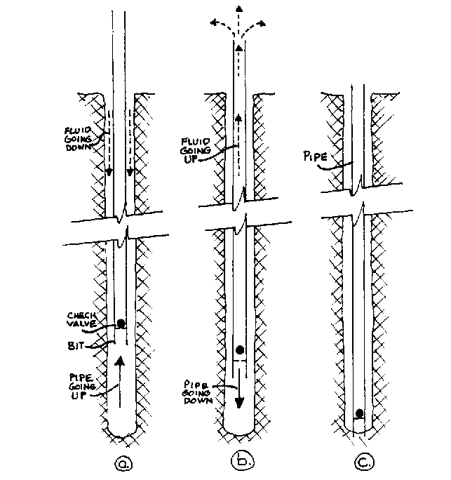
the hole. (See Fig. 13-1.)

FIG. 13-1. SLUDGER DETAIL
(a)As the pipe is lifted, there is room for more fluid to flow down into the hole,
(b) Dropping or pushing the pipe down forces fluid and cuttings to come up through the valve into the pipe and, after several strokes, out the top.
(c.) When the pipe strikes the bottom of the hole as you drill, the valve closes, preventing the fluid in the pipe from flowing back down into the hole.
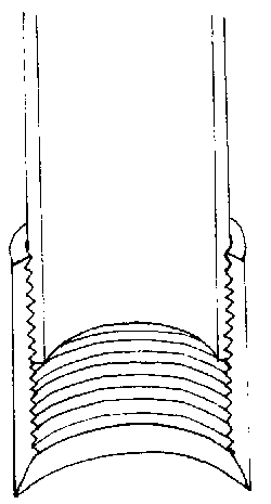
The cutting action is performed by a bit attached to the lower end of the tool string. This can be simply a sharpened or jagged edged coupling that is screwed on to the bottom length of pipe. The bit strikes the bottom of the hole at the end of the downstroke and acts to loosen the material which can then be picked up by the drilling fluid to be removed from the hole. (See Fig. 13-2.)
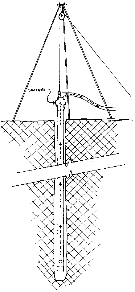
Several variations of this technique have been used effectively. Wells have been sunk using standard pipe and coupling as the bit while a person uses his/her hand to act as the check valve by covering and uncovering the top end of the pipe. Hollow drill pipe with a swivel joint attached on the top has also been used. (See Fig. 13-3.)
Where a motorized lifting apparatus is not available, more and more labor will be required to lift and drop the drill string as it gets longer and heavier.
This particular sinking method is the only one that uses drilling fluid to remove drill cuttings from the hole but does not need a special pump. Normally the pump is required to move the fluid so that it will pick up the drill cuttings but with this technique the drill string itself acts as the fluid pump.

FIG. 13-2. SHARPENED COUPLING

FIG. 13-3. SLUDGER METHOD USING SWIVEL
2. Advantages and Disadvantages
Here are the major advantages of using this technique:
very few tools are required;
the work is completed quickly;
the subsurface conditions are easily determined from 1) cutting samples taken from the drilling fluid issuing from the top of the drill pipe and 2) the rate of descent of the tools.
The major disadvantages are:
the method requires that water be available;
rocks larger than medium sized gravel cannot be penetrated.
3. Equipment
Cutting bit: A regular pipe coupling can work as a cutting bit if the edges are sharpened. File or grind only the inside edge of the coupling to avoid narrowing the diameter. (See Figure 13-2.)
Check valve: A valve prevents the downward flow of liquid in the drill pipe. Ball valves are commonly used. Where materials are scarce a well worker could use his/her hand to cover the top of the pipe when it is lifted, lifting the hand as the pipe is dropped. (See Fig. 11-6.)
Drill pipe: Metal pipe which can be coupled together in suitable lengths as needed to provide necessary drill string height is usually used.
Swivel hose connection to top of drill pipe: A water discharge piece is not absolutely necessary, although it is useful in helping to channel the water to a specific location rather than having it come directly out of the top of the drill pipe. (See Fig.13-3.) Depending on the lifting apparatus used, a flexible hose could even be connected directly to the top of the drill pipe although it may become damaged with the continual up and down motion adding stress to it.
Lifting mechanism: This can be made of local materials and be whatever you think appropriate. Some options are:
- a tripod with pulley and rope and some way to pull and release the rope;
- a springpole;
- a capstan made of an empty rear car wheel;
- a lever type assembly attached directly to the pipe by means of a rope or chain. (See Fig. 116.)
Hand tools
An assortment of hand tools is always handy at a well site. When using metal pipe,pipe wrenches will be almost indispensable.
4. Sinking Process
Arrange and set up all tools, equipment and supplies. Leave the area immediately around the well clear of materials that do not have to be there. Set up the lifting device and locate it appropriately. A tripod should have the pulley centered over the hole. A lever type arrangement should have the end of the lever adjacent to the hole.
Start the hole in non-caving formations by sinking a hole as far as possible with a post hole digger or spade. In caving formations drive a section of pipe down so that the top end is slightly below ground level.
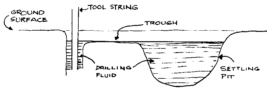
Dig out a settling pit appropriate to the water discharge piece. With a swivel type discharge head or where water can be channeled to one location, dig a settling pit on one side of well with a small channel feed for water from the pit to the hole. With no discharge piece,the only alternative is to make the settling pit a circular shape around the hole. The problem with that arrangement is that it allows too many cuttings to fall back into the hole.
Fill the settling pit and hole with water. (See Fig. 13-4.)

FIG. 13-4. MORE FLUID WILL NEED TO BE ADDED TO ALLOW CONTINUOUS CIRCULATION THROUGH HOLE AND SETTLING PIT.
Assemble the tool string,which consists of a bit, check valve, drill pipe and discharge piece. Set the tool string upright in the hole, and attach it to the lifting device.
Begin the drilling operation by raising and dropping the tool string. The harder the material being drilled, the more rapid and shorter the strokes should be for the best results. Up to 120 strokes per minute may be desirable for shales, sandstone and limestone. The softer the material being drilled, the slower the stroke should be, from 30 to 60 strokes per minute in clays, loose sand, and gravel. In extremely soft material take care not to let the bit sink too far into the formation, thus plugging the bit or valve and making removal difficult. The best and safest method is to allow the bit to cut and mix the cuttings so that no chunks large enough to clog it are passed up the pipe. When threaded pipe is used in the tool string, it should be continually rotated in a clockwise direction to help ensure that the connections stay tight and a straight round hole is being drilled.
Add more drill pipe when necessary as the hole is deepened. As the string becomes heavier it will require more and more power to lift it.
It is also necessary to add water as the hole is being sunk to keep the hole full. The settling pit may need to be cleaned out to prevent excavated material from flowing back into the hole with the drilling fluid.
When a good water-bearing layer is reached there is usually a noticable drop in drilling fluid level. Continued pumping action will produce water and if sufficient quantity of water is produced drilling can be stopped. Drilling fluid will also noticably drop when some dry sand, or gravel formations are reached. In this case it will be necessary to increase the weight (thickness) of the drilling fluid with additional clay, to help seal the hole and prevent fluid loss. (In this situation the casing could also be driven in to reinforce the walls.) Rice hulls, wheat chaff, cow dung or other material can also be added to the fluid but the more and coarser the sealing material used the more difficult it will be to develop and clear up the well later. Excessive use of hulls or straw-loaded material may later plug the well screen and render the well useless.
Casing - As in most other sinking methods, the casing can either be installed after the hole is sunk or driven down as the hole is sunk.
- Casing the hole after it is completed is usually possible because drilling mud will tend to reinforce hole walls to prevent them from caving. Remove the drilling tool string and start the first section of casing pipe. It will usually have to be driven. Use a drive shoe (sharpened coupling) on the bottom of the casing to protect it. Add more sections of casing pipe as necessary. After the casing is driven it will be necessary to remove the material that will have accumulated inside the casing. This will not be difficult because the accumulated cuttings will be loose.
- Casing the hole while drilling proceeds is only necessary where the hole caves in, hampering drilling efforts. The casing is driven down as drilling proceeds so that the bottom of the casing is at the same level as where the tool is working. Water will then have to be introduced into the casing pipe, probably by hand because the casing will be sticking up above ground level, preventing drilling fluid from entering the hole. When this happens, the inefficiency of the "pumping" process through the drill pipe may not permit water to be pumped up high enough above the static water level in the casing pipe (which will go down as pumped) to come out of the discharge piece.
The hole is drilled and cased to the maximum depth possible, to the bottom of the aquifer, or until the water-bearing layer has been penetrated far enough to produce the desired amount of water.
Sink and develop the bottom section of the well. Most often the casing and well point are driven into aquifer.
NOTE: Where a single well is being sunk, the drill pipe could also be used as the casing if it is sealed tight to prevent water seepage down around the casing.

