


| Drilling and Casing Techniques |
A. Introduction
Small diameter well sinking techniques include:
techniques that
require large, expensive equipment;
techniques that need only small equipment.
Large scale
techniques are covered here in enough detail to understand their
basic operating principles. These methods use large, expensive, complicated machinery
whose detailed operation can be adequately understood only with the
benefits of hands-on training. However, the basic drilling techniques used
with these larger rigs are, in many cases, the same
as those which can be used with smaller equipment and
may serve to better illustrate the possible variations of each
technique.
Small scale techniques are covered later in
enough detail to enable interested persons to perform them.
B. Drilling Techniques with Large Scale Equipment
1. Types of Rigs
These techniques all use
a specially made unit known as a "rig" which includes
all of the different power systems needed to operate one
or a variety of types of drilling tools. The cost
of these rigs ranges from about $20,000 to $500,000 and
up. Depending on the type of rig and the drilling
method, holes can be sunk with diameters ranging from 4
cm to 1.4 m. (See Fig. 11-1.)
There are two basic types of large drilling rigs, percussion rigs
which give an up-and-down motion to the tools and rotary
rigs which turn the drilling tools.
By far
the most common type of percussion rig is the cable
tool. Drilling tools are suspended on a cable which is
alternately pulled and released to create the up-anddown motion of
the tools. When drill cuttings have accumulated to the point
that they impede the action of the bit, it is
removed from the hole and a bailer is lowered, usually
on a second cable, to pick up the cuttings. This
is one of the two most common methods of well
drilling and is known as cable tool percussion. Cable tool
rigs are also adaptable to other forms of percussion drilling
such as hydraulic percussion and jet percussion. These other percussion
techniques are not, however, commonly practiced.
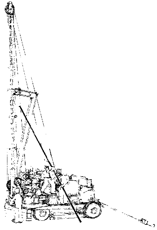
FIG. 11-1. CABLE TOOL PERCUSSION DRILLING RIG
Unlike percussion,there are several different relatively common types of rotary rigs. The biggest of these, and perhaps the most complicated of all well drilling machinery, is the rig capable of hydraulic rotary drilling and its variants. This and the cable tool are the two most commonly used water well drilling rigs.
Other types of rotary rigs are those that use augers and core drills. Auger rigs are designed to drill relatively large diameter holes to a relatively shallow depth in non-caving formations. Core drills are designed to drill very small diameter holes to great depths and recover samples of all the materials drilled through. Both of these kinds of rotary drills have been used to drill water wells, although both have limitations for such use.
NOTE: When considering using this equipment, carefully check the manufacturer's size specifications. There has been much confusion and delay resulting from the fact that tools and equipment are commonly manufactured in both English and Metric sizes, which are not generally compatible. To compound the problem there are many different kinds of thread patterns in use which can be cut on either English or Metric pipe sizes.
2. Drilling Variations
There are a number of possible drilling variations given the two basic methods, percussion and rotary, depending on whether or not a fluid is used and which way it is circulated.
percussion only - cable tool percussion.( See Fig. 11-2a.) This is commonly used to sink wells through all kinds of formations.
percussion and regular fluid circulation - jet percussion. (See Fig. 11-2b.) This method is no longer frequently used but where wells are jetted from the surface it is usually a form of jet percussion.
percussion and reverse fluid circulation - hydraulic percussion. (See Fig. 11-2c.) This method is not commonly used with large machines, although the small scale version, known as the sludger technique, has been extensively used in some areas.
rotary only - auger.(See Fig. 11-2d.) Augering or boring is commonly used to drill relatively shallow holes for wells and many other uses.
rotary and regular fluid circulation - hydraulic rotary. (See Fig. 11-2e.) This method is commonly used to drill wells through all kinds of formations.
rotary and reverse fluid circulation - reverse circulation. (See Fig. 11-2f.) Reverse circulation drilling has the same uses as hydraulic rotary and is sometimes perferred.
rotary and air as drilling fluid - air rotary or downthe-hole hammer. This is a relatively new technique which uses compressed air as the drilling fluid and is most suitable for drilling through rock.
The following two techniques are not really primary drilling techniques since they are not often used with large drilling equipment to sink wells from the ground surface. They are, however, frequently used in well drilling operations to sink the well screen and casing into place in the aquifer after a hole has been drilled down to the water table by any of the above techniques. For more information, see Chapter 14.
regular fluid circulation only - jetting or washing. (See Fig. 11-2g.) The fluid itself loosens the soil at the bottom of the hole and also carries the loosened soil to the surface.
no fluid circulation - driven. (See Fig. 11-2h,) With this technique the casing and well screen are simply pounded into the ground.
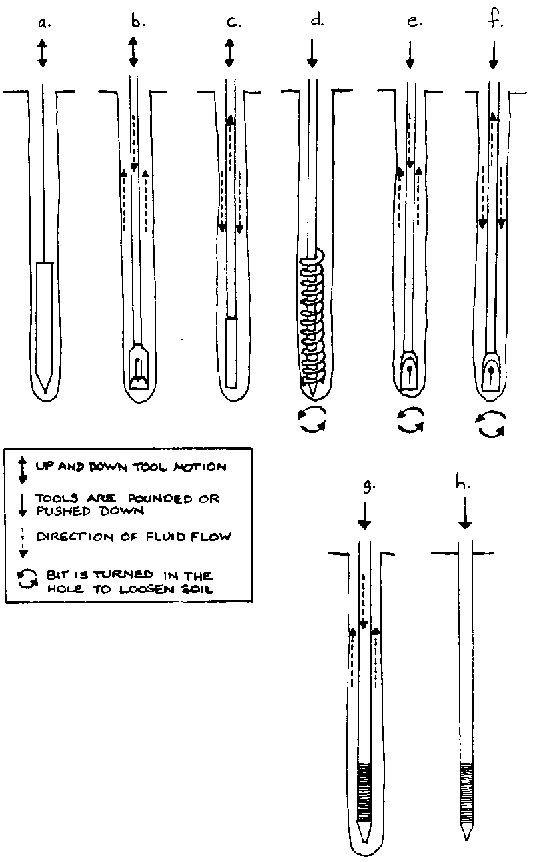
FIG. 11-2. DRILLING METHODS. THE CHOISE OF DRILLING METHOD DEPENDS MAINLY ON WHAT MATERIALS ARE AVAILABLE.
3. Drilling Depth
Assuming that the rig and tools are appropriate for the particular ground formation being penetrated, the depth that can be drilled is limited only by the ability of the rig to lift the tools from the hole.
For example, one particular manufacturer provides the following suggested depth capabilities for their topofthe-line hydraulic rotary drilling rig fitted out with various drilling tools.
|
drilling method |
hole diameter |
depth |
|
auger |
900 mm |
12 m |
|
continuous flight auger |
300 mm |
15 m |
|
reverse circulation |
600 mm |
150 m |
|
air rotary |
170 mm |
450 m |
The same company's core drilling rig is capable of drilling a 48 mm diameter hole to 1400 meters.
C. Overview of Small-Scale Techniques
1. Introduction
The small-scale techniques given here have been adapted for use with a minimum amount of equipment and expense. These techniques may require only hand tools, pipe, and a great deal of labor, or they may require a tripod, a motor pump, drilling pipe, and drill bit plus whatever material will be permanently installed in the well. Wells workers may select from a variety of equipment varying in cost and technical difficulty, all of which are less expensive and less complicated than a drilling rig.
These sinking methods may be used in largely consolidated ground formations (see Glossary). The suitability of the different methods varies with the degree of caving expected and whether rock will be encountered.
It is common practice to use more than one method to sink the complete hole. With adequate finances and equipment, it is helpful to use the particular technique most suited to the (1) ground conditions, (2) expected depth of water, and (3) the section of well being worked on.
Each individual small equipment sinking technique is generally limited to use in a certain type of soil. Where the soil layers to be penetrated are similar, using one appropriate sinking technique will be most efficient. However, it is much more likely that you will encounter several different soils, requiring the use of variations on a single sinking technique, or even different techniques. When evaluating the various sinking techniques, choose the one most appropriate to a particular situation. You may also want to consider what other equipment might be needed in different ground conditions.
In many cases, ground conditions will vary between the middle and bottom sections of the well. The same type of soil may surround the complete well, but where that soil is saturated with water (bottom section), its drilling characteristics will usually be different. For example, a sand or combination of sand and gravel aquifer will usually be subject to caving, making it impossible to excavate a hole down into the aquifer without sinking a casing with the drilling tools. Sand that is only damp, on the other hand, will tend to stick together and not cave in.
However, if rock is struck, the well must be moved to a different site where rock might not be encountered, or the workers must switch to drilling tools appropriate for rock. Hand-powered tools commonly used in unconsolidated formations generally gouge and slice through soil to loosen it. This is not suitable for rock, which must be smashed and chipped or broken into smaller pieces in order to be removed from the hole.
2. Sinking Methods and Ground Conditions
There are then three basic types of ground conditions that can be encountered while drilling.
|
Ground Condition |
Suitable Sinking Technique |
|
Rock |
percussion |
|
Loose, non-caving |
rotary, percussion or sludger |
|
Loose, caving |
driven, jetted |
Where all three ground conditions are likely to be encountered you should be equipped with the types of tools appropriate to each.
3. Level of Complexitv and Common Uses of Small Scale
Techniques
a. techniques that require the least equipment and expertise
driven - Variations of this technique are used in almost all methods. By itself it can only reach a limited depth in relatively loose soil.
sludger - This is a specific adaptation of a percussion technique which uses a drilling fluid but does not require a pump during drilling. The technique is quick and there are good possibilities where the ground permits.
b. techniques that require a minimum of manufactured equipment but require that materials and semiskilled labor be available to produce the necessary equipment.
hand percussion - This excavation technique works in the widest range of soil conditions. However, it is slow and requires considerable hard labor. Although it is simple, there are many possible minor variations which could affect drilling but which require some experience to use effectively.
hand auger - This is one of the simplest and most easily understood methods for simple field work. It is limited to non-caving formation without rocks bigger than the auger. It is also slow and can only reach a limited depth.
c. techniques that require at least local manufacture of the necessary equipment and pumps.
jetted - This technique will only work in the same places that the sludger method will and it requires more equipment and expertise. It will, however, usually be faster and require less work than sludger.
D. Small Equipment and Drilling Techniques
Here is basic information on small equipment drilling techniques, which provides the following information on each method.
materials required;
quick description of method;
suitability of ground conditions;
cost;
work;
depth.
1. Rotary hand auger
Materials required - auger, drill stems to connect the auger bit with the handle, and a handle.
The particular operation will depend on the exact bit being used. Most often the bit is turned in the hole until it is full of drill cuttings. It is then brought to the surface, emptied, and returned to the hole. This process is continued until the desired depth is reached or ground conditions change causing this method to be unusable. (See Fig.11-3.)
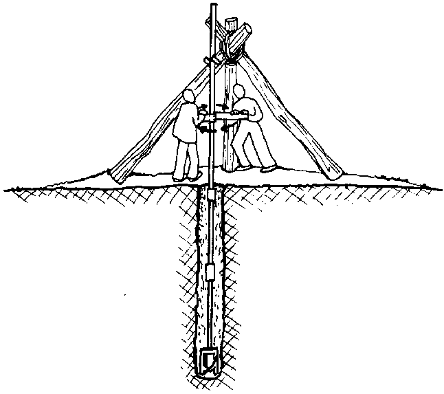
FIG. 11-3. HAND AUGERING
Suitability to ground conditions - This method can be used in clay, silt, and sand formations not subject to caving. In caving formations a casing slightly larger than the bit can be driven down as the hole is sunk. Where rock is reached this sinking method will have to be discontinued.
Cost - The U.S. cost of a 10 cm diameter auger, drill stem, and handle in the spring of 1978 was $16.50.
Work - Unskilled workers can easily be taught to use this method to sink and finish wells up to 20 m deep in five days.
Depth - 20 m is the usual maximum depth.
2. Hand percussion
Materials required - You will need a chopping bit (see Fig. 11-4), bailer (see Fig. 11-5), either drill shafts or rope, and a tripod and pulley to assist in lifting and dropping the drilling tools.
The bit is lifted and dropped until it has loosened so much material in the bottom of the hole that its progress is stopped. The bit is then removed and the bailer is dropped into the hole to pick up the cuttings. The bailer is worked to pick up as much as it can and then removed from the well and emptied. The bit can then be lowered back into the hole and worked as before. This sequence is continued until water is reached or the ground conditions change to necessitate a change in sinking technique.
Suitability of ground conditions - This sinking technique can be used to sink wells in all kinds of ground conditions although it can be very slow in hard rock.
Cost - The cost of hand percussion tools will depend on the sophistication and quality desired but, compared to most other methods, these tools are cheap and easily made.
Work - Unskilled workers can easily be taught to use this method although semi-skilled supervision will be necessary for optimum performance.

FIG. 11-4. CHOPPING BIT
Depth - Great depths are possible in optimum ground conditions but as the hole gets deeper more and more time will be spent switching back and forth between the bit and the bailer because of the greater distance they must be raised and lowered.
This method is best suited for drilling through soft rock and well packed, non-caving soils. It can be used in hard rock although progress will be slow and drilling bits will need to be sharpened frequently. It can also be used in caving soils if the casing is driven in as the hole is sunk.
3. Hand percussion and fluid (sludger)
Materials required - You will need metal pipe and couplings, a cutting bit which can be made from a coupling, pipe wrenches, and a tripod or lever structure with which to lift and drop the metal pipe.

FIG.11-5. BAILER
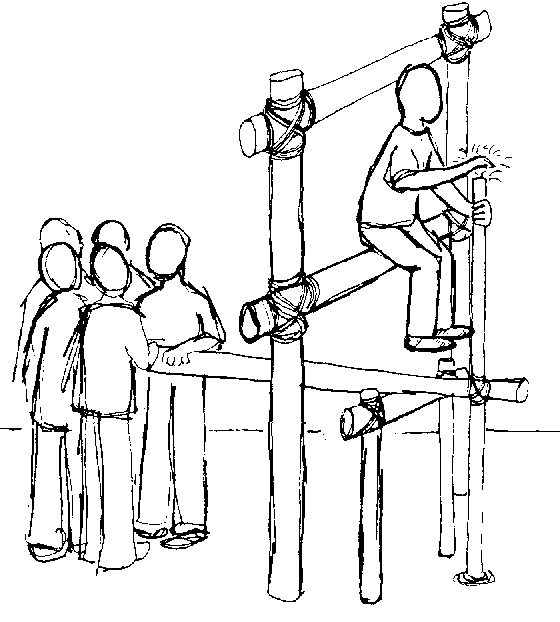
FIG. 11-6. SLUDGER TECHNIQUE
The pipe string equipped with a one-way valve is lifted and dropped into the hole which is full of drilling fluid (usually water). The one-way valve permits fluid and cuttings to flow up through the pipe but not down. The upand-down action of the pipe, acting with the valve, allows the tool string to act as a pump removing fluid and cuttings from the well. The fluid can be recirculated if cuttings are allowed to settle out. (See Fig. 11-6.)
Suitability to ground conditions - This may be used in fine or sandy soils as long as rocks are no larger than mediumsized gravel.
Cost - Obviously the cost will vary from place to place, but to give an example, wells using this technique drilled with 1.5" G.I. and finished with plastic casing cost 12¢ to 16¢ per ft. in Nepal in 1976.
Work - Six relatively unskilled men can build a 4 cm diameter 60 m deep well in four days.
Depth - Maximum 80 m.
4. Driven
Materials required include a drive point, a casing pipe, a drive cap to protect casing pipe when driven, and a heavy weight to strike the cap.
Driven wells are sunk by pounding a special type of well screen called a drive point (well point) into the ground. The drive point is attached to the casing pipe and more casing pipe is added as necessary as the whole string of casing pipe and drive point is driven down. (See Fig. 11-7.)
Suitability to ground conditions - This method is generally used and easiest to drive in loose, caving formations. It will not go through rock and sinks through clay only with difficulty.
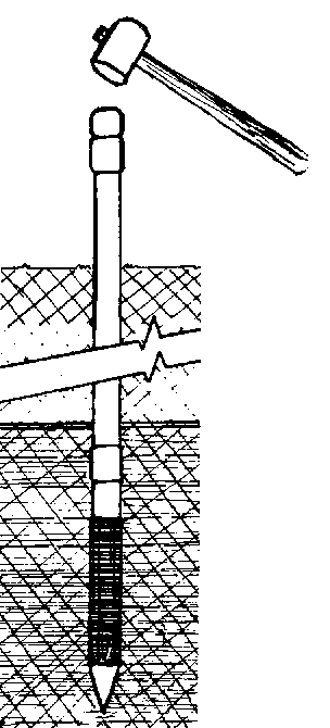
FIG. 11-7. DRIVEN WELL
Cost - As of August 1976,a 91 cm long, 5 cm diameter, stainless steel, continuous slot drive point cost $80.14 and a 305 cm length of 5 cm diameter seemless, ungalvanized (black), steel casing pipe cost $43.65 in the U.S. These are manufacturers' prices and are given here merely as examples. Acceptable substitutes for both of these can usually be locally manufactured.
Work - The majority of the work involved in sinking a well with this method is lifting and dropping a heavy weight to drive the pipe into the ground.
Depth - Wells can usually not be driven more than 10 m by hand or 20 m be machine because of the friction between the casing pipe and the soil.
5. Jetted
Materials required include a pump, hoses, a watertight connection of the hose to the top of the drilling string, a hollow drill pipe, a hoist, and a jetting bit.
Jetted wells are sunk by pumping drilling fluid (usually water) down through the drill pipe and out a special jetting bit. This works on the -same principle as a flowing garden hose that can be pushed into the ground. The washing action of a stream of water alone can be used to sink small diameter pipe and well screens in sandy formations. (See Fig. 11-8.)
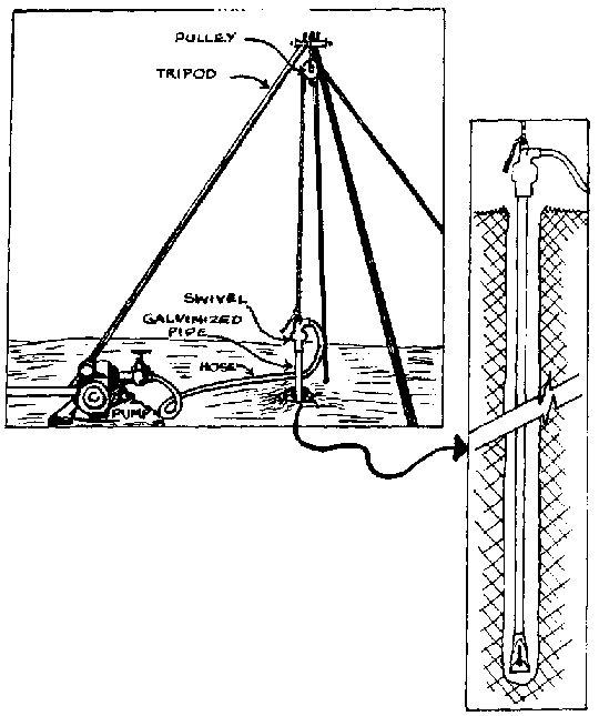
FIG. 11-8. JETTED WELL
Suitability to ground conditions - Jetting with percussion can be used to go through all but hard rock formations. It is commonly used to sink small diameter well screens in water bearing sand.
Cost - Because of the equipment necessary, this sinking method is more expensive than the other techniques covered here. Its actual cost is difficult to estimate because of the wide range of equipment possibilities that can be used. A simple hand-operated diaphragm pump can be used to sink one long pre-assembled length of casing into place at a cost comparable to other methods discussed.
Depth - Jet percussion builds wells 8 to 10 cm in diameter up to 60 m. With simple equipment, a well can be jetted to a depth of about 20 m.
Work - This method requires some technical skill, experience, and judgment, although all of these are straightforward and easily understood by people with modest technical backgrounds.
E. Casing Installation
1. Overview of Casing Techniques
How the casing is installed in the well depends on such factors as casing materials, and ground conditions.
Before the casing is set into place it is very important that you also consider how the well screen will be attached to it. (See p. 192.) If the casing above is set in place the well screen must later be telescoped into place. Special tools and materials are then required to seal the well screen to the casing.
The same three methods of installing the casing are possible whether or not the well screen is attached.
Lowering the casing into the hole - Where the drilled hole will remain open without caving for a long enough period of time, the casing can simply be lowered into the completed hole. Normally, the casing is lowered as far as possible into the hole, after which it can be sunk further by one of the following methods.
Driving the casing - This method can only be used where heavy metal pipe, which will not deform as it is driven, is used as the casing. It can be used in all but very hard formations although it is most often used in loose caving formations. (See p. 163.)
The casing can be driven into place either after the hole has been sunk as far as possible or as the drilling proceeds. The latter is used primarily with percussion techniques where a bailer can be worked inside the casing to remove loose, caving types of soil as the casing is driven in to reinforce and maintain the hole. In this instance special drive clamps must be attached around the casing pipe so that it can be driven while the bailer is inside it.
When the casing will be driven into place before the well screen is attached, a sharpened coupling can be screwed on to the bottom of the casing to facilitate sinking. (See Fig. 11-9.)
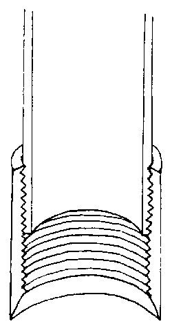
FIG. 11-9. SHARPENED COUPLING
Washing the casing into place - This method uses the process of pumping a fluid down through the pipe to remove loosened soil particles from the hole and allow the casing to sink. The only difference between this and the jetting process described on page 176 is that a special jetting bit which directs a high velocity fluid stream at the bottom of the hole is not used. Because this method requires that the pipe joints be watertight, it generally is used only with manufactured pipe. It also requires the use of a pump, to force water down through the casing, and a watertight connection at the top of the casing through which the water can be pumped. (See p. 239.)
2. Sealing the Casing
Once the casing is set in its final position in the well any space around the casing should be filled in. The top three meters of this space should be filled with mortar or concrete to seal the casing to the ground formation and thus prevent possible contaminants from easily flowing down along the outside of the casing pipe .

