

| Introduction to Drilled Wells |
A. Overview of Small Diameter Wells
1. Basic Features
Small diameter wells usually have
diameters of less than 50 cm and can be as
small as 2.5 cm. For the purposes of this manual,
all wells that are sunk by using tools from the
ground surface, and therefore do not require that people go
down and work in the well to sink them, are
small diameter wells. They are also called "drilled" wells, "tube"
wells, or "boreholes."
Small diameter wells normally require
a pump to supply water on demand at the surface.
These wells are usually small enough so that a bucket
used to lift water from a large diameter well will
not fit into the well. A special water lifting device
must then be built and installed in the well to
allow people to draw water.
There are many
different kinds of water lifting devices that may be used,
ranging from a modified bucket arrangement that will fit in
the well to a motor-powered turbine pump capable of delivering
thousands of liters per minute. This manual emphasizes pumps that
will comfortably supply enough water to meet the minimal needs
of the local population.
Every small diameter well
is sunk by using the same arrangement of equipment. At
the ground surface is a power unit which supplies the
necessary motion to sink the hole.
At the bottom of the hole is a cutting tool (drill bit)
which, when moved in a certain way, loosens whatever soil
or rock is beneath it in the hole. (See Fig.10-1.)
Between the power unit and the bit is
a connecting mechanism that transmits the motion of the power
unit to the cutting tool.

FIG. 10-1. DRILL BITS
2. Drilling Motions
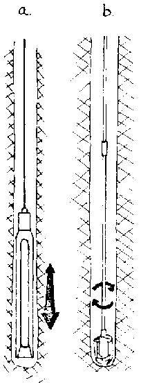
Because of the size and shape of small diameter wells and the equipment required to sink them, there are only two different kinds of drilling motion that are used (Fig. 10-2 ):
a. up and down - called percussion
b. around and around - called rotary

FIG. 10-2. DRILLING MOTIONS
All well sinking equipment is intended to use one of these two different motions. However, all such equipment is designed to use one or the motions predominantly and often the other motion in some secondary capacity. Thus, tools that use an up-anddown motion are referred to as "percussion" tools because they rely on their downward fall to stike and loosen ground materials. Tools that must be turned to gouge and scrape ground materials are referred to as "rotary" tools for obvious reasons.
Both of the different types of equipment can be adapted for use in most ground conditions. However, when using simple hand powered variations of either of these techniques there are certain limitations which will be noted later.
3. Removal of Drill Cuttings from the Hole
In order for the cutting tool or drill bit to effectively do its job of loosening the soil at the bottom of the hole, the soil and rock that it has already loosened or chipped away must be removed so as not to hinder the bit's continued operation. There are several different techniques and tools that can be used.
A special tool can be lowered into the well to remove the drill cuttings. For example, a bailer, which is essentially a hollow tube with a valve at the bottom end, can be lowered to the bottom of the hole and then dropped, to pick up the drill cuttings. When the bailer is dropped onto a pile of drill cuttings, the cuttings force the valve open as the bailer falls down around the cuttings. When the bailer is lifted, the valve closes, allowing the bailer with the cuttings inside it to be lifted to the surface and emptied. (Fig. 10-3)
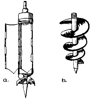
The cutting tool itself can be used to remove drill cuttings from the hole. For example, auger bits which arc screwed into the ground remove soil by either accumulating the loosened soil inside the bit (see Fig. 10-4a) which will have to be emptied regularly, or by forcing the soil upwards as the bit is rotated. (See Fig. 10-4b.)
A fluid can be used to continually pick up drill cuttings and carry them to the surface. Fluid is normally pumped down through the drill rod and out of holes in the bit where it picks up drill cuttings and carries them back up through the hole.

FIG. 10-3. BAILER

FIG. 10-4. AUGER BITS.
4. Equipment and Materials
Here are the equipment and materials that are usually employed (see Fig. B for illustration of Materials):
hole sinking equipment: Choose equipment which is appropriate to the particular ground conditions.
hand tools: Each sinking method will require a specific set of hand tools. Example of tools that are often needed include pipe wrenches, screwdrivers, tape measures, and hack saws.
lifting/lowering equipment: This equipment is always useful but the particular sinking technique chosen and the depth of the well will determine whether it is necessary.
casing: This pipe is used to hold the hole permanently open to allow the use of pumps.
well screen: This allows water entry and prevents the entrance of aquifer material.
water lifting device (see Pumps!: This pulls water out of the narrow casing pipe.
material to build platform around well head (cement preferred).
5. Casing
A pipe is installed in a well to prevent the hole walls from caving in and provide a conduit through which water can be brought to the surface.
If a well is sunk through anything other than consolidated rock, it will need to be cased to assure a permanent hole.
The casing extends from just above the ground surface to the top of the well screen which is at the bottom of the well.
Commercially drilled wells are usually cased with steel pipe which is either welded together or coupled, using specially threaded couplings. Although plastics are being used increasingly because they will not rust or corrode, nevertheless they cannot be driven into the hole as required by some drilling techniques and ground conditions. Basically, any cylindrical product which can be installed in the hole to prevent its collapse will work. For small diameter shallow wells, galvanized iron pipe, clay tile, bamboo and even hollowed logs have been used, although the last two are, for obvious reasons, not recommended.
NOTE: Before using steel or even galvanized iron casing, test the water to obtain some kind of measure of its corrosive properties. In Liberia, wells with steel casing had life spans of as little as six months due to corrosion.
6. Well Screen
This is the water intake section at the bottom of the well. It is about the same diameter as the casing and is made as long as is necessary a) for the depth of aquifer and 2) to produce the amount of water needed.
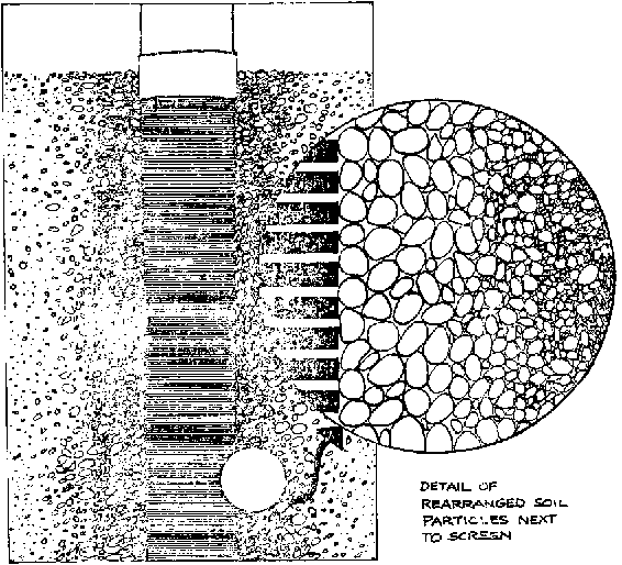
The screen itself acts both as a filter and as a medium through which the soil particles immediately surrounding the screen can be rearranged to permit easier and better water flow into the well, a process known as well development. Wells are usually developed by rapidly forcing water in and out of the well screen. This removes the fine soil particles from right next to the screen leaving only larger soil particles with larger spaces between them,thus permitting more and easier water movement into the well. (Fig. 10-5)
The different kinds of screens are discussed in detail in Chapter 15.

FIG. 10-5. CONTINUOUS SLOT WELL SCREEN IN DEVELOPED GROUND FORMATION
B. Design of Drilled Wells
The basic objective of well design is to achieve the best combination of materials, techniques, and cost to produce a well which is useful to a local community. Against a background of scarce material and financial resources, the design of wells for small rural communities in the developing countries requires a flexible approach to individual water supply needs that involves compromises on the allocations of community resources.
1. Design Problems
Two major problems in all water improvement projects: a) system maintenance and b) water testing and treatment should be considered in the design and planning of the well.
Maintenance is the major problem in water development. A system cannot last anywhere nearly as long as expected unless regular maintenance is performed on the system and the usual minor problems are fixed as they happen.
Water testing and treatment:
Water is rarely tested to determine its chemical and bacteriological characteristics. Chemical testing is necessary to determine possible appropriate materials for intake and pumping equipment, as well as potability. Bacteriological testing is needed to detect possible disease-carrying organisms. Many simple, inexpensive, and relatively effective methods of treatment are available and could easily be used to help ensure water potability and to lower disease rates. (See Appendix VIII.)
2. Diameter
Where large supplies of water are needed, the normal procedure for determining the well diameter is to:
determine the quantity of water needed;
find the size of the pump needed to deliver a certain quantity of water per unit of time which is lifted a certain distance (head);
choose casing that is slightly larger than the pumping equipment;
excavate a hole whose diameter can accommodate the required casing. (See p. 145.) This presumes finding one or more aquifers that can deliver the quantity of water needed.
For small wells, the same general considerations apply, although based on the selection of the most appropriate equipment available. The casings in most of these wells will be between 5 cm and 10 cm in diameter.
3. Depth
Where it is possible to get any idea of what the depth of the well will be, a sinking method must be chosen that is capable of reaching that depth.
Where small water supplies are being developed, the usual Practice is to develop the first major aquifer, reached by sinking the intake section as far into the aquifer as possible with the given equipment, until a sufficient supply to meet local needs is assured.
The possible depth of the well sunk with handpowered drilling techniques is usually about 20 meters except where a fluid is used to remove drill cuttings,in which case wells can often be sunk deeper.
4. Choice of Pump (Also see Pump Appendix.)
The largest commonly manufactured hand pump cylinder will fit in a 14 cm hole.
The deeper a well is, the smaller the diameter of the pump cylinder used.
It may be difficult to introduce hand pumps on previously open wells where the depth is greater than 30 meters. The reason is that people who probably had been using animals to draw their water will be required to do the pumping themselves.
If the well is properly developed, most small diameter wells cannot be pumped dry with a hand pump.
C. Planning
Overview
Here is an overview of planning which presents major choices and their determining factors. Use it as a checklist in your planning activities.
a. How you sink the hole depends on:
ground conditions: What ground conditions do you expect? Are you prepared to go through rock? How much rock must be penetrated?
sinking methods: What sinking methods can you use in these ground conditions?
equipment: What equipment do you have? How accessible is it? Which equipment is suitable for the ground conditions you expect? (See Small Equipment and Drilling Techniques, p. 137.)
b. How you case the well (reinforce the hole walls) will depend on:
material: What material will the casing be made of? What casing material would be suitable for the chemical and bacteriological characteristics of the water to be tapped?
ground conditions: If loose, caving formations are encountered, it may be necessary to sink the casing along with the excavation to keep the hole open and thus allow continued sinking. It is not necessary to case a hole that is sunk into solid rock, although if the hole continues on through the rock into another unconsolidated formation, the entire hole should be cased.
sinking methods: The casing can be lowered into the hole after the hole is excavated or driven along with the excavation process.
c. How the intake section is constructed will depend on:
materials: What kinds of screens can be built locally or are commercially available? What effect will different possible choices of screens have on well production?
ground conditions: The aquifer depth and particle size will determine the optimum length and opening size of the intake section.
sinking methods: The method used to sink the intake section can determine the type of well screen that will be used.
casing: Whether the casing is sunk along with drilling or lowered into the completed hole will determine the type of screen connection to the casing.
d. How the top section is constructed will depend on: 1) the degree of sanitary protection that is felt necessary and 2) users' preferences for a particular method of water delivery.
e. The maintenance performed on the well depends on:
the arrangements made for regular maintenance.
the community involvement and interest in the well throughout the construction process.
the understanding of the connection between improved water supplies and better health.
D. Work Outline
Here is an outline of the essential construction activities, in working order:
Community awareness and education activities should be in progress so that actual construction can serve to illustrate ideas that have already been presented.
Gather and arrange supplies at the well site. Planning the placement and use of supplies around the well can make work more efficient and easier.
Excavate hole (sink hole, dig or drill hole). The hole is sunk as near to the desired depth as possible. This will often include sinking the hole as far as necessary into the aquifer, as ground conditions permit.
Case hole (line and reinforce walls). (See p. 145.) In all wells except those sunk through hard rock, a casing must be installed to prevent possible collapse of hole walls. For small diameter wells, the casing is usually pipe.
Excavate bottom section. If the bottom section cannot be sunk by whatever method was used to excavate the middle section, then another sinking method which is more appropriate to the ground conditions will have to be used.
Install a well screen. (See p. 122.) A well screen is a filter which enables the development of the surrounding aquifer to allow as much water and as few aquifer particles as possible to enter the well. The well screen can be attached to the casing and installed with it. Or it can be installed separately after the casing is in place.
Seal top 3 m of casing. Grout around the casing clown to at least 3 m below the ground surface, to help prevent surface contamination from entering the well.
Construct a platform around the hole which, by gently sloping away from the hole (1:40 slope), allows water to run off, preventing accumulation and possible well contamination from surface water seeping in around the pump.
Install a pump or water lifting device which conforms as much as possible with local water gathering customs and practice.

