


| Construction of Ferro-Cement Reservoirs |
| Construction of Ferro-Cement Reservoirs |
In Reservoir Without Mouldą section, detailed advice was given on the entire procedure of building a ferro-cement structure. This and the following chapter will only mention the differences in the technique employed. This means there will be no advice on curing the plaster and concrete, including the repeated covering with plastic sheets and splashing with water. The general plastering technique will be named but not explained in detail. Mixing the plaster, testing, sifting the sand etc. are explained in Chapter 3, and remain the same for all types of ferro-cement tanks and waterproof plastering of reinforced bricktanks. The advantages or disadvantages of the various tank structures should first be established by consulting section catchment possibilities and choice of reservoir types.
The mould is an expensive capital investment which, if carefully handled, is good for ten to fifteen structures. Since it involves the bending of corrugated galvanized sheets as well as welding, it should be manufactured by a well-equipped.workshop experienced in this type of work.
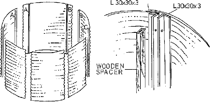
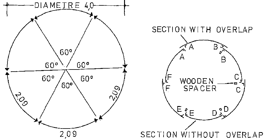
The mould is constructed in six sections. This is necessary to reduce the weight and make it easy to handle, especially when it has to be removed from inside the tank. The sections are fabricated from rolled sheets of corrugated iron, joined together by mild steel angles (30 x 30 x 3 mm). These steel angles are fixed by spot welding to the corrugated sheets. Three of the sections have overlaps, being 30 mm wider on each side than one sixth of the circle, Fig. 5.29. The other three sections are exactly one sixth of the circumference. The example given in Fig. 5.29 shows a diameter of 4.00 m with a height of 1.85 m. This makes a tank of 20 mł capacity. The sections are bolted together with timber spacers. These spacers are to be made after all the welding is done and the mould is to be assembled for testing. The timber spacers are made to cover up unequal parts of the mould and should therefore be made specifically for each joint. They also serve to ease the dismantling of the mould after the wall has been made. The overlapping of the mould sections are to prevent mortar passing through during plastering. Test assembly should be performed on an even and horizontal base, preferably a concrete floor. After all holes for bolts are drilled, the mould should be bolted together. The single parts of the assembled mould including the timber spacers must be marked clearly, so that after dismantling, reassembly is always done in the same way. It is best to number the parts and paint the numbers on the inside with oil paint. Do not forget to number the spacers as well. The spacers should be made of hardwood and oiled afterwards. If carefully handled they can last for some time, but are easily replaceable, Figs 5.28, 5.29.
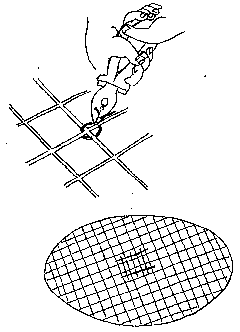
Different soil conditions require different foundations. The foundation slab can be constructed as described in section Reservoir Without Mouldą. If welded reinforcement mesh is not available, it can be substituted by one layer of fencing mesh combined with one layer of chicken wire. If reinforcement rods are available, any size above 4 mm diameter can be used to produce a mesh as shown in Fig. 5.30 by tying crossed rods with binding wire. The squares should not exceed 150 mm. If only reinforcement bars of 10 mm or more diameter are available, the squares can be enlarged up to 200 mm, but in this case one layer of chicken wire should be fixed to the self-made mesh.
If you intend to cover the reservoir with a concrete slab, there should be a pier in the centre of the tank to support it. This requires double reinforcement in the centre of the floor slab. The concrete slab can only be constructed if sufficient reinforcement is available. If this is not the case, the roof can be constructed as a ferro-cement dome, as described in Chapter 5.1. If you intend to choose this type of roof there is no need to double-reinforce the centre of the floor slab, since a pier to support the roof is not needed.

 4. Foundation on unstable ground
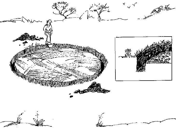
In general it must be said that any foundation on unstable ground remains a ask. Sometimes it is advisable to choose another place where ground conditions are more favourable. But, as explained already for reservoirs, there are not many suitable places if the best catchment position is to be achieved. In the case of unstable soil the best and usually cheapest method is to exchange the soil. After marking the area of the tank foundation, extend the radius for another 500 mm and excavate all soil which is not stable, even if you only reach the stable soil at a depth of 1.00 m. If, for instance, even at this depth stable soil occurs on one side but the other side is still unstable, continue to excavate until your entire ground appears to be stable enough for the structure. Now find backfilling material. This can be old bricks and gravel. Natural hardcore is preferred. Fill this material in layers of not more than 300 mm and compact mechanically by pile-driving. Do not backfill more than half a metre per day and fill the compaction with water overnight. Next morning first pile-drive the work from the day before. After the backfill is finished, keep compacting for one week, filling up with water once a day and recompacting the following day. Then construct a concrete slab foundation as described in section Reservoir Without Mouldą.
Another method to be applied whenever there is uncertainty about the soil conditions is the ring foundation. Mark the external diameter of the slab and then mark another circle reducing the radius by 500 mm. Between the external and internal circle dig out a trench of 400 mm depth, Fig. 5.31. Do the same in the centre in a square or circular shape of 600 mm (in case you need a pier). The bottom of the trench must be levelled and recompacted. The same applies to the area inside the circle. The foundation and slab area is now ready for reinforcement. See Chapter 6 for reinforcement of foundation. Follow the advice given there for the construction of the slab too. Make sure it will be level and smooth, otherwise there will be problems in assembling the mould. Before concreting the slab, do not forget to place the water tap unit as shown in Fig. 5.8.
5. Assembling the mould and placing the reinforcement
The mould is in six sections, each marked to ensure that they are assembled in the correct order. Tapered wooden spacers are used between the frames to make it easier to remove the sections (Fig. 5.28).
Assemble the mould loosely near the base and check that all the pieces are present and fit properly. This should be done before the mould is required.
Find the centre of the slab and mark a circle on the slab the same size as the mould to ensure the mould is centred on the base.
Take the first section A-B and place it on the line. Take the second section B-C, and place it on the line with the overlap outside the first section and the letters matching.
Place the wooden spacers between the metal flanges and bolt them together loosely.
Do not tighten until all sections are assembled.
Bolt the remaining sections together in the correct order (B—C, C-D, etc.) until the mould is loosely assembled.
Using the circle on the slab as a guide, move the sections until the mould is circular and in the centre of the slab.
Tighten all bolts.
Place paper at the bottom of the mould to prevent oil from spilling on the concrete. Using shutter oil (or old engine oil) paint the outside of the mould. If oil does get on the concrete it should be cleaned off. Make sure the mould is oily, but that no oil runs off.
Ensure the mould is in the right position. Check this by measuring the distance from the mould to the edge of the concrete slab. Do not start reinforcing until the mould is assembled and stable.
Wrap the chicken mesh around the bottom of the mould once with approximately SO mm tucked under the mould to the inside, Fig. 5.32.
When you have reached your starting point, pull the chicken mesh, cut it and tighten it, overlapping by 100 mm, then start again above the first circle, overlapping the already fixed mesh by about 100 mm. If the height of the tank requires a third circle of wire mesh, do the same again, overlapping the second circle by 100 mm.
Wrap the chicken mesh around the top of the mould. The top layer should overlap the mould by approximately 100 mm and the remainder is folded over the top of the mould.
Wrap 8-gauge fencing wire around the outside of the chicken mesh, starting at the bottom. The corrugations are used to keep the spacing even. The wire should be wrapped with two wires in each corrugation for the first eight corrugations from the bottom, and then once per corrugation up to the top three, which again should have two strands each.
Use the thin tie wire to fasten the chicken wire to the fencing wire to prevent it from slipping, Fig. 5.33.
7. External plastering of tank was
Also see section Reservoir Without Mouldą and general advice for material and mixing in Material Testing and Mixing.
Mix the first batch of mortar (1 :3 cement: sand, as stiff as possible). Make the first batch small, about one wheelbarrowful. Although the method of application is similar to plastering a wall, progress will be slow at the beginning. Make sure the mortar is stiff and not too wet. If it is too wet it will slip and leave cracks in the plaster which should not happen at all.
Start plastering at the bottom and work up. Try to work evenly around the tank. But remember there will be another external coat so if the plaster is not very even and smooth this can be put right with the second coat.
Apply the first coat thinly. Make sure all the corrugated iron is covered but some of the wire can still be left showing. You will experience that the more plaster you try to apply for the first coat, the more difficult it is to prevent the plaster from slipping. The right technique can only be learned by experience.
Leave a hole at the top for the overflow, about 100 mm below the top of the mould. Ensure the mortar remains damp by covering the finished parts with plastic. This is especially important in bright sunlight and on hot summer days.
The second coat can be applied as soon as the first coat is stiff enough, and so it is possible to do both on the same day. However if there is any doubt it is better to leave it until the following day.
Remember that the mortar will require wetting and covering when finished.
Mix the mortar in the same way as the first coat (1 :3 cement: sand; -stiff).
Plaster up from the bottom uniformly.
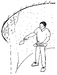
Plaster as thinly as possible but be sure all the wires are covered. Smooth the surface using a wooden float. This is the outside
finish of the tank, so try to make a smooth surface.
Keep plaster damp while you work —do not let it dry out. When the second layer is completed, dampen with water and cover with plastic immediately: Leave to cure for at least one full day.
Fig. 5.34 shows the ferro-cement wall with the mould still fixed. After completing the second layer of plaster, the tank should be left at least one full day before removing the mould.
Remove all bolts.
Remove all the timber spacers.
Starting at joint A-A, pull the edge of the inner panel A-B.
If the panel sticks, lever off gently using the flange of the adjacent panel. Do not knock the shutters as the plaster will still be soft and can be easily damaged.
Remove panel A-B completely.
Repeat with panels C-D and E-F.
Remove panels B-C, D-E and F-A.
Inspect plaster inside and outside for damage.
Wet inside and outside of plaster.
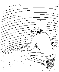
9. Internal plastering of the tank wall
Before you start this work remove all leftover oil visible on the plaster. This must be done very carefully, washing away with lots of water.
It is possible to plaster inside the wall of the tank as soon as the mould is removed but, as before, remember that the plaster must be applied in one continuous layer. If you are not sure there is enough time for this, start the next morning. But do not forget to cover the wall. Access to the inside should be via a scaffold or ladders as shown in Fig. 5.16. Under no circumstances should the wall be exposed to any load. At this stage even vertical load should be avoided.
Clean the overflow hole of mortar and put the pipe in position. The overflow should start about 100 mm below the top, since the reinforcement at the top should not be cut.
Bend up the wire that was left inside at the bottom of the mould. Plaster only up to l 00 or 150 mm above the floor slab.
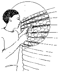
Plaster inside the tank in the same way as the outside, using a 1 :3 mortar mix, as stiff as possible, and applying the plaster as thinly as possible. The plaster should just be thick enough to fill the corrugations. Cover the wire completely and provide a smooth finish using a wooden float, Fig. 5.35.
The chicken wire pulled underneath the mould should be tied in the corner. Prepare a mortar fillet in the corner between wall and floor as shown in Fig. 5.36 or apply the technique as shown in Fig. 5.23.
Using additional mortar, ensure the top of the wall is smooth and level. Trim the high points if necessary, but do not cut off the chicken wire bent inwards.
Make sure that all the plaster is damp and cover immediately with the plastic sheets as soon as it is finished.
Prepare the nil coat and apply it as described in Chapter 5.1.7.
This layer acts as a final finish and seal to the tank base.
Roughen the bottom of the wall to ensure a good bond between the screed and the wall, cleaning it of all dust.
Wet the mortar filet and the base slab.
Mix mortar using a dry mix of 1 :3 cement: sand.
Apply a thin screed, approximately 15 mm thick over the floor slab, starting from the fillet and working inwards. Finish the surface of screed by 'shining', i.e. dusting the surface of the screed with cement and using a steel float to produce a very smooth surface.
Dampen walls and floor and cover the tank completely with the plastic sheet.
Alternatively apply the technique described in section Reservoir Without Mouldą.
Leave floor screed to set for at least two days, covered in water, before starting the next stage.
Mark the centre of the tank.
Build a brick pier 230 mm wide in the centre up to the level of the top of the tank wall.
Plaster the pier with 1: 3 mortar (cement: sand) to produce a smooth finish.
Dampen all walls and the floor, and cover the tank with PVC sheeting.
Leave the pier and wall for at least a full day before starting work. Making the roof shuttering may damage the walls if it is done too soon after plastering.
Check the inside diameter at the top of the tank.
Mark a circle on the ground with the diameter of the inside of the tank
Cut the sheets of shutter ply in half, lengthwise, to make strips 600 mm wide.
Place the strips of ply over the circle to cover it as efficiently as possible and mark their positions.
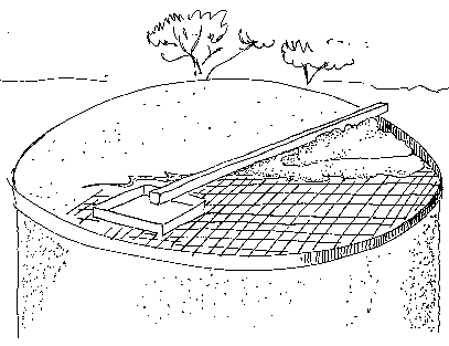
Construct the supporting structure of poles and rafters inside the tank, ensuring that the top surface of the ply will be level with the top of the wall. Nail the rafters to the vertical props.
Starting at the side opposite the manhole, lay the sheets of shutter ply on the rafters and cut to shape. Nail the ply to the rafters.
Make an opening in the shutter ply at the manhole, as all the inside timber has to be removed through it later. The opening should be 650 x 650 mm.
Fill all gaps in the shutter or between shutter and wall with paper or plastic.
Lay a damp proof course on top of the tank wall.
Cut hardboard into strips 300 mm wide, or use hardboard from the slab.
Tie the hardboard around the top of the tank to form an edge shutter so that this edge is 100 mm above the wall.
Form an edge shutter for the manhole. This should be 75 mm deep and slightly larger than the hole in the shutter (650 x 650 mm) so that it can rest on the shutter.
Paint the shutter with shutter oil or old engine oil.
preparation area cut a piece of reinforcement mesh to the size of the circle. If this is not available use 6-mm reinforcement mild steel and tie together in the same way as the floor reinforcement.
Place the reinforcement in the shutter and either support it with 20-mm plywood blocks or distribute about four wheelbarrows of concrete in the shutter and place the reinforcement on top of this concrete. Ensure that the reinforcement is 20 mm above shutter level.
Double the reinforcement in the centre above the pier which will support the roof.
The concrete used must be of good quality and care should be taken in selecting the sand and stone. See section Material Testing and Mixing.
Start at the side furthest from the manhole and work evenly towards the manhole opening.
Use a straight piece of timber, the edge shuttering and manhole shutter as guides to form a smooth surface as the concrete is laid (Fig 5.37)
Do not remove the shutter until seven days after the roof slab was cast.
Remove the shutter as gently as possible, starting at the middle.
Remove the shutter from next to the walls last and do not lever or strike the tank walls. Clean all shuttering material and remove all nails.
Save the shuttering for reuse.
After you have removed all shutter material, start to clean the floor carefully. There should be no dust left. If there is any damage in the floor, repair with mortar 1: 1 sand and cement using only sifted sand. Wet the floor for one day or night and apply the nil coat. Since the nil of the wall only goes down to the mortar fillet, this must also be covered with nil. After this job is done, the main structure is finalized. Prepare the manhole cover according to Fig. 5.26.
Remember the tank now has to be filled with water at least to a level of 100 mm to keep it wet. If it is possible the entire structure of the reservoir should be sprayed with water twice a day for at least one week. If this cannot be assured, it should be covered entirely by plastic sheeting to avoid drying off.
16. Alternative roof structure
If there is not enough reinforcement mesh or rods to be used for making a mesh on the site, it is possible to prepare a roof of ferro-cement by applying the technique described in Chapter 5.1. This type of dome roof does not need a pier to support it. Special care has to be taken when the dome reinforcement is placed on the wall. The bottom circle line must have a ring wire tightly fixed to the reinforcement.
After the reinforcement dome has been placed in position on
top of the wall, the ring reinforcement of the wall
must be tied to the ring reinforcement of the dome
using binding wire. The chicken wire projecting beyond the top
of the wall should be neatly fixed to the dome reinforcement.