
| Gutters and Downpipes |
The efficiency of any rainwater catchment depends to a great extent on the gutter and downpipes. Qualified tinsmith's (or plumber's) work is demanded to fix gutters for catchment. Large roofs especially need precise workmanship. Often workers are seen using ladders, rather than scaffolding, but precise gutter fixing cannot be achieved without a scaffold on the overall length of the cave.
The slope of gutters should be about 0.3-0.5%. This first of all requires precise measuring. However in rainwater catchment, a slope of 0.3 -0.5% often remains theory. As an example: an eave length of 30.0 m would require an overall slope of 90-150 mm from the end to the outflow. But gutters fixed 90 mm below the eave are likely not to catch heavy runoff. Under normal circumstances the problem would not occur as one would furnish a roof eave of 30.0 m with at least three downpipes. This would not only solve the problem of sloping but also reduce the size of the gutter, as the catchment area per outflow is much smaller. In rainwater catchment maximum runoff is to be drained into the reservoir and compromises must be made.
After scaffolding has been erected under the roof overhang, the eave must be checked to see if it is horizontal. Sometimes this is not the case, particularly with long roofs. To measure and compromise the slope a thin wire is to be stretched tightly along the length of the eave and attached to a nail on both ends. If this method is used, a 50-mm overall slope could be obtained for the gutter. This is admittedly next to nothing. However the system will also work if the gutter is absolutely horizontal and straight. Whatever minimum slope can be achieved this first of all serves the purpose to ensure that there will be not even the slightest slope in the opposite direction. Large gutters are usually square. They should not be fixed on horizontal brackets but have a slight slope toward the outside (see drawing No. 8). This means viewing the cross-section of the gutter which must show a minimum slope from the eave corner toward the opposite corner. This will help to increase the rate of draining.
A common mistake observed is the underdimensioning of the gutter bracket. It has to be kept in mind that during heavy downpours gutters can suddenly be filled with water and their weight might increase up to 40 kg/m. To avoid deformation or even collapse of large gutters, brackets must be strong and at distances not exceeding 1.0 m. Brackets for large gutters should never be fixed on purlines only. If the distance between the rafters makes an intermediate support necessary there are two ways of solving the problem. One is to have two different strong types of brackets, the stronger fixed at the rafters, the weaker ones at the purline in between the rafters. The other, often easier, method is to exchange the purline for a much stronger and larger one.
In rainwater catchment downpipes often channel the water over long distances (from one gable side to the other) with a slope of sometimes only 1.5%. In all those cases they are not working as downpipes but rather as covered channels. As a result the downpipes sometimes develop a weight similar to the gutters and must therefore be securely fixed to the wall. Usually downpipes are of smaller dimension than gutters since water falls more or less vertically. In rainwater catchment this is often not the case and downpipes should be of the same dimension as the gutters they are linked to.
Reservoirs at public buildings are often large and, so as not to block the passage, sometimes more than 2.00 m away from the building. In those cases the downpipes must be bridged from the building wall to the tank inflow. It is necessary to suspend the bridged downpipes or to support them. Suspension is done if the wall above the bridge point is high enough. A steel clamp must be put around the downpipe in the centre of the pipe bridge and this fixed by a steel rope with a strong hook plugged into the wall. This has to be done in such a way that gable wall, pipe bridge and steel rope form a triangle. If it is not possible to suspend the pipe bridge, it must be supported. This is done by fixing a welded triangle of steel angles at the wall underneath the pipe bridge. Any pipe bridge must at least be supported or suspended in the centre if it exceeds 1 m in length.
Calculation of gutter and downpipe dimensions
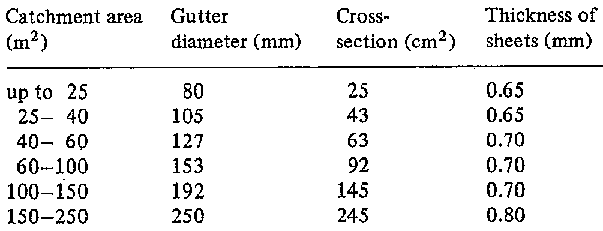
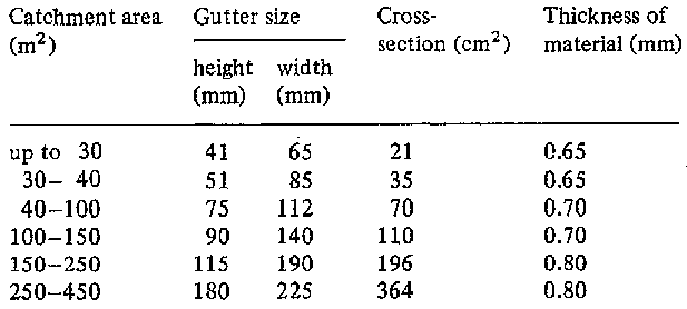
General rule 1.0 cm² cross-section of gutter and downpipe per m² catchment (roof) area.

Table 15

Table 16
Example: Catchment area 8.0 x 30.0 m = 240.0 m², cross-section of gutter and downpipe 240 cm². According to Table 15 you can choose a gutter of half-round shape, inner diameter 250 mm or following Table 16 a squared gutter, height 115 mm, width 190 mm.

