

| The Reinforced Bricktank |


| The Reinforced Bricktank |
In most cases, it might be appropriate to engage a contractor to build the reservoir. There are several reasons why this is recommended. A contractor is accustomed to organizing material supplies and the work at the site. He knows his staff, and can arrange for the best artisans for the more complicated work. Usually, a contractor is equipped with the necessary scaffolding and shutter material. The larger the reservoir to be built, the more important these become. On the other hand, the contractor probably has no experience with this type of structure. To cope with the different possibilities, this chapter deals with aspects of the construction work in a similar way as with the ferro-cement tanks. Chapter 6.2 provides Standard Specifications and Bills of Quantities to allow tendering of the proposed reservoir. Chapter 6 should provide the necessary information for supervising the construction work.
It should be stressed that, in all cases where tank structures are made at the site, qualified staff are needed. This means, first of all, experienced plasterers are required for ferro-cement structures, as well as for bricktanks. The bricktank requires bricklayers and plasterers, but as these are more or less the same trade, there are few differences between them. While ferro-cement reinforcement can be done by skilled artisans not necessarily experienced~ in the technique, it becomes more difficult-with bricktanks, as qualified reinforcement work must be executed. In many countries, reinforcement binding is a different trade. In this chapter, however, schedules and drawings have been made in such a way as to simplify reading them.
The relatively heavy reinforced foundation for this type of tank may cause surprise, but one must remember concrete is not ferro-cement, and it differs in its properties. Reinforced concrete and brickwork are not as elastic as ferro-cement, It is important to know there are two different forces which influence the structure; one is the soil settlement, the other temperature expansion. Both forces should be controlled by the reinforcement. Cracks in the foundation must not occur because of slight soil settlement, as cracks lead immediately to leaking. Slight soil movement can occur even after years (e.g. tree roots can create soil movement). Temperature variations can be tremendous. In the sun, a reservoir can develop an outside surface temperature of 90°C or higher, while the water in the tank might be 25°C or less. Temperatures on the outside of the tank may also vary. For example, the side of the tank which is in the shade could reach only 30°C. The case becomes even more complicated depending on the amount of water in the tank. If the tank is filled to one-quarter capacity or less, the outside heat could warm up the entire thickness of the wall of the upper part of the tank. Therefore, as demonstrated, there could be totally different temperatures at different points of a reservoir at the same time, and these temperature tensions must be kept under control by reinforcing the brick wall. Experience has shown that the temperature influence becomes clearly visible if a reinforced brickwork reservoir is plastered outside with cement plaster. After some time, microcracks occur. These cracks are not structurally important, but influence the appearance. For this reason, if possible, brick reservoirs should not be plastered outside with cement mortar. Cement mortar also increases the cost of the project, and in most cases is not used, but is replaced with a white plaster limewash which reflects the sun and partially reduces temperature tensions. Plastering bricktanks is sometimes desirable, however. Such a case might arise if the bricktank was constructed together with a new house. The house should be located in line with catchment needs, and the reservoir, although a large structure, should harmonize with the house when covered with lime plaster with a rough surface. As lime is more elastic than cement, fewer cracks will result and, if the surface is rough, they may never be visible.
Procedures for Construction Work:
-Choose the reservoir size according to the advice given in Calculation of Rainwater Volume. Remember it is usually cheaper to build one large reservoir than two smaller ones which add up to the same capacity. Figure 6.1 shows a 68-m3 reservoir built at Hill School, Lobatse, Botswana, where rainwater from three roofs is drained into one tank.
-Mark the diameter of the tank foundation on the ground to make sure no passage is blocked by the proposed reservoir. Methods of bridging downpipes are explained in Gutters and Downpipes.
-In Tables 8-14 (p. 88-91) the amount of material required is specified, including a calculation for wastage. Sand for mortar and the number of bricks required are based on a brick size of 110 mm x 230 mm x 70 mm in Southern Africa. If your brick size differs considerably, you must recalculate the number of bricks and the amount of sand and cement required for bricklaying. Slight differences should be ignored. In Botswana, cement bricks have been used, but burned clay bricks can be used if available according to standard. As tests for quality need to be made in a laboratory, finding out about the quality of a brick on the work site is very difficult. If the supplier cannot submit a certificate, and there are doubts about the quality of the bricks, they should be sent for testing before they are used. For example, if a back is not as hard as it should be for brickwork, you can rub dust off it with your hand. Bricks should be hard-burned and blue in colouring, rather than red in colouring. Burned bricks often differ in size. This makes working with them more difficult and requires skilled bricklayers. If bricks differ in length, build up the wall from the inside to achieve a smooth surface, as this is the side where the waterproof plastering must be done.
- When the material is on site, and arrangements have been made for securing storage space, mark the external diameter of the foundation on the ground. Different techniques for unstable ground are discussed in Chapter 5.2. In principle, these techniques are the same as those required for the reinforced bricktank. The foundation trench can be dug only after the topsoil inside the circle has been removed. All measurements given in the technical drawings assume the ground is stable. In cases where topsoil is not of equal depth, it must be removed to the greatest depth required to hit stable ground at all points (e.g. if the topsoil is about 300 mm in depth, it must be dug out entirely, as the foundation can only start at that depth). When all topsoil has been removed to stable ground, levelling can begin. If there is no topsoil, a foundation should be dug to 100 mm before the trench is dug. This is usually necessary to avoid soil erosion. If there are pockets of topsoil after a layer of 100 mm has been removed, they must be filled with lean concrete. When all topsoil has been removed and the stable ground has been levelled, the ring foundation should be dug as shown in Figure 5.3.1. Measurements for the size of the ring foundation and the thickness of the slab are the same for all tank sizes. All tanks with an internal diameter of 5.5 m or more require a centre pier to support the roof slab (for foundation see technical drawing).
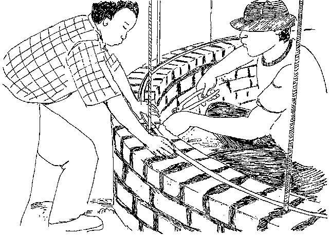
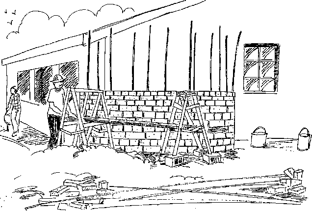
Reinforcement work must be done on site, but a metal workshop should probably bend the stirrups, as they must be of equal size and shape. Dimensions given for the rods are the minimum. It is always possible to increase the dimensions if the scheduled size is not available. For the wall reinforcement, this is crucial. Vertical rods in the wall and ring reinforcement, which can be done with 6-mm rods, should not exceed 10 mm in diameter. This is necessary, as rods cannot disturb the brick bond or the joints which are equal in size. As Figure 6.4 shows, the reinforcement must be placed in the centre of the wall. It is therefore imperative to fix the vertical rods precisely onto the foundation reinforcement and to make sure they are not dislocated during the process of concreting the foundation and ground slab. The horizontal ring reinforcement must be tied to the vertical bars from inside, using binding wire and pliers as shown in Figure 6.2. As the joints can be only 10 mm thick, and the reinforcement steel must be covered entirely by cement mortar, any dimension exceeding the one indicated will cause problems. Reinforcement not covered with cement mortar will rust. Therefore, flush-jointed bricklaying is necessary. To maintain the required height and assure an equal and. solidly filled brick wall, all courses should be indicated on a timber board which should be used as a control mechanism. As shown in Figure 6.5, keeping all vertical bars in position while bricklaying is usually difficult if the height of the tank exceeds 2.00 m. For taller structures, rods can be cut into two pieces, extending the one fixed into the foundation in such a way that it overlaps the other rod by at least 100 mm. The rods should be tied tightly together, above the 1.50-m mark.


Seating roof slabs is a crucial detail. As previously explained, temperature variations can be tremendous, and these create movement in the slab which is difficult to control. Therefore, provision must be made for this movement so that it does not create structural damage. A sliding joint is the best way to control this movement. Technical drawing No. 3 illustrates two different types of sliding joints. The first method is as follows: the top of the tank wall must be plastered with a smooth surface, and finished with a steel trowel. This plaster should be applied after the second coat of plaster has been applied to the inside of the tank, and then must be separated from the wall plaster by cutting through the fresh plaster in the form of a V-joint. In this method, shuttering the slab height should be done with hardboard strips nailed to the outside of the wall, exceeding the plaster slab seating by 60 mm or 80 mm, depending on the dimension of the slab. Two layers of thick plastic foil or bituminous roof felt must then be laid on the plastered seating. This will allow expansion of the slab without creating cracks in the wall. The second method can be used if hardboard for shuttering is not available, but requires strips of softboard or a material with similar properties. The shutter for the slab height is one course of half-stone, as shown in technical drawing No. 3. The remaining half-width of the wall is sufficient as slab seating. Again, the seating must be plastered and two layers of plastic foil must be put under the slab. There must be 15 mm of softboard stripping between the wall and the fresh concrete to prevent the expanding slab from pushing the half-stone wall which acts as a permanent shutter. This material should be removed a few hours after finishing the concreting and the open space should be cleared. Although this method is not as good as the first method described, it will serve the purpose if it is properly implemented. If the slab still pushes the half-stone course, it is easy to remove the entire course and, by doing this, the problem of visibility of movement is eliminated It must be stressed that the seating for the slab on half the wall is sufficient, but the lintel must be seated on the whole width of the wall.
Waterproof plaster should be handled with special care according to standards described in Material Testing and Mixing. Waterproof plaster consists of three coats, each applied to the previous coat while still fresh. Keeping the plaster fresh is often a major problem in hot, arid climates, but this can be done by covering the fresh plaster and by splashing it with water before applying the next coat. Plastic sheets make the best covers.
First Coat:
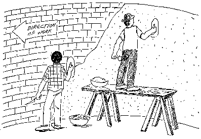
Before plastering, make sure the wall is moist. Make sure there are as many labourers on site as required for the job, and organize the work in such a way that the mixing, delivery and application of the plaster can be accomplished in a continuous fashion. Remember even a large tank must be completely coated in one operation. This is best done by having two teams of plasterers working at the same time, but starting opposite each other, -working anti-clockwise towards the other team's starting point. Figure 6.6 shows two plasterers working in the same direction: one on the floor and the other on a scaffold. The plasterer on the floor starts plastering an area larger than the area covered by the scaffold. The scaffold is then moved to the wall and the second plasterer starts plastering the upper wall, while the first plasterer continues on the lower part of the wall. There should be no joint between the two working areas or at the meeting point. This might require extra curing of the meeting point until the coat of plaster is closed.

The first coat of mortar should be composed of three parts river sand and one part cement, as described in Chapter 3. The river sand must be passed through a screen sieve not exceeding 3 mm. If a 3-mm sieve is not available, the sand used in the first coat can consist of the same core size as used in the second coat. The first coat should be a minimum of 10 mm thick and wooden-floatfinished. Before the second coat is prepared, the wall must be covered from the inside with plastic sheeting to prevent it from drying out.
Second Coat:
The second coat differs from the first, as the sand must be passed through a screen sieve of 1.5 mm, as required for ferro-cement. This process is described in Chapter 3. This coat should be a minimum of 5 mm thick, and wooden-float-finished. The working procedure is the same as that of the first coat. Before starting the second coat, the first coat must be wet, and the starting point should be changed so the meeting points of the first and second coats do not coincide.
Third Coat:
If the second coat can be applied in less than a day' the third coat can be applied when the second coat has been finished. The third coat is the 'nil coat' composition, as described in Material Testing and Mixing. As the third coat is applied with a steel trowel, and is no thicker than 2 mm, it can be applied quite quickly. Remember the nil coat should be applied in one continuous process, and make sure enough cement is prepared before starting. as the nil coat consumes about one 50 kg bag of cement per five square metres. The nil coat should not cover the lower 100 mm of the wall, as the corner must be executed as shown in Figure 5.23.
Floor screed mixture should be of the same composition as the first coat of plaster. After the screed is mixed, apply it to the corner with a glass bottle, as described in Reservoir Without Mouldą and Figure 5.23. The nil coat should be applied to the floor the following day, and two-three hours after finishing the nil coat application, the floor should be covered with water for at least three days.
When handling the formwork for the roof slab, make sure the floor is not damaged.

