¦ ¦ ¦ ¦ ¦
ENVIS Technical Report 123,   August 2017
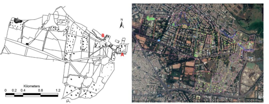
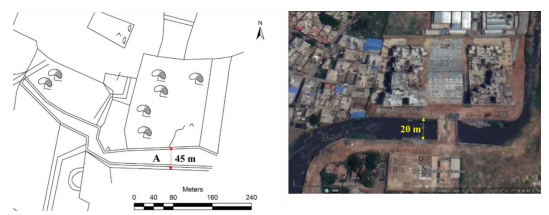
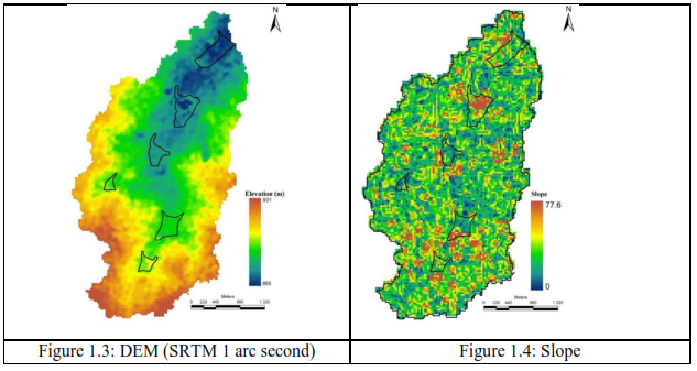
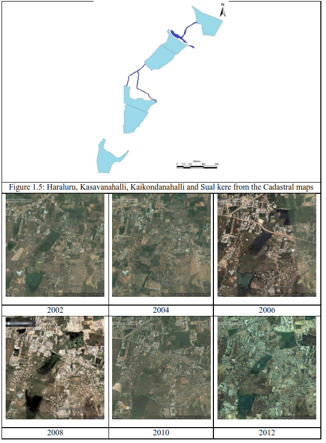
Frequent Floods in Bangalore: Causes and Remedial Measures
Energy & Wetlands Research Group, Centre for Ecological Sciences, Indian Institute of Science, Bangalore, Karnataka, 560 012, India.
E Mail: cestvr@ces.iisc.ernet.in, Tel: 91-080-22933099, 2293 3503 extn 101, 107, 113
Narrowing and Concretisation of storm water drains


Storm water drains – implications of concretization: Impaired Ecosystem Functions - bioremediation and groundwater recharge (but maximization of benefits to consultants with frequent floods)

During the field work on 1 May 2017 along with CEO, KLCDA it was observed

  1. Rajakaluve (storm water drain) connecting Bellandur lake from city market side is narrowed to 28.5 m against the original width of 60 m and also violating recent NGT guidelines. This is mainly to help the encraochers of storm water drains while bypassing NGT’s guidleines of storm water drain buffer regions
  2. Concretisation of storm water – this would affect the hydrological functional ability of storm water drains – ground water recharge, remediation and flood mitigation
  3. Concretization and narrowing the drains has only enhanced the flooding in the city, observed recently (15th August 2017, 24th August 2017).
  4. BBMP while wasting the public money has made Bangalore landscape vulnerable with frequent floods.

Figure 1.1 shows revenue map of Jakkasandra village which is in the upstream of Bellanduru lake. Figure 2 illustrates narrowed width of rajakaulve between 1908 and 2017. It can be noted that nearly 50% of the channel width is reduced and has been concretized.

Figure 1:Jakkasandra Village map
(Note : A  indicates the Rajakaluveys measured for change in width)

Figure 1.2: Rajakaluve A: from Agara Lake to Bellandur Lake


Case study of select drains in the Kaikondanahalli Lake catchment (next pages, Table 1.1, Figure 1.3-1.4), highlights the implications of narrowing and concretising storm water drains and the need for sensible interventions.
  1. Drains (trapezoidal) are to be designed in the city to optimise natural hydrological principles;
  2. No concretization of drain bed – natural bed (soil) would help in (i) retarding velocity, (ii) infiltration – recharge of ground water resources. This would help in mitigating floods. Soil also acts as membrane and aids in remediation, preventing the contamination of ground water resources;
  3. Concretisation of storm water drain would increase the quantity of water flow (due to absence of infiltration) and enhances water velocity (10-12 times, Refer Table 1.2). This would certainly increases the city’s flooding vulnerability with high intense rainfall coupled with the increase in paved surfaces (78% of Bangalore land surface is paved!). Consequent of this would be higher instances of flooding with the damages to the property and human life;
  4. Let the drain walls be either stone pitched (for structural stability) or turfed with grasses depending on the location;
  5. Chain link fences to prevent un-authorised occupation of drains and also dumping of wastes;
  6. Evolve appropriate policy mechanisms to make dumping of solid waste, construction and demolition waste in the drains and lakebed cognizable and non-bailable offence;
  7. Make drain and lakebed encroachments as cognizable and non-bailable offence and imprisonment of 12 months;
  8. Strengthen legal cell in BBMP to address all illegalities (nexus of mafia - contractors, engineers, etc.) as well as encroachments;

Need to move away from contractor with consultant driven design to maximise individual gains (through cement concretization etc.) -Estimate of Rs 8 crore per kilometer of drain is too exorbitant and waste of public money.

Kaikondanahalli Lake Catchment

The catchment of Kaikondanahalli Lake has an area of 11.03 sq.km which joins downstream of Bellandur lake. This catchment has 6 lakes in the upstream. The catchment is dominated by infrastructural (residential and commercial) establishments. Salient features of the catchment area are as given in table 1.1. Elevation map is as described in figure 1.3, slope in figure 1.4 and the revenue map in figure 1.5, Change in landscape between 2002 to 2016 is as depicted in figure 1.6.

Figure 1.6: Landscape dynamics between Kasavanahalli, Kaikondanahalli and Sual kere


Open Channels Flow: Flow of fluids in natural or manmade channels whose surface is exposed to the atmosphere and flow is due to gravitational force are referred to as open channel flow. In order to understand the channels capabilities or designing the channels, Manning’s equation is generally used. Mannings equation is a function of channels physical properties such as wetted perimeter, cross sectional area, bed slope, bed material, depth of flow, etc.
Manning’s equation for velocity of flow is given by :

Where
V is the velocity of flow in the channel as m/s
k is constant (1 for SI units and 1.46 for FPS units),
n is Manning’s roughness coefficient (Table 1.2).
R is the hydraulic radius which is defined as the ratio of Cross sectional area (A) to Wetted Perimeter (P)

S is the bed slope of the channel.
Discharge (Q) cum/s is quantified as function of Area (A) sq.m and Velocity (V) m/s
Q = A.V

Table 1.1: Salient Features of the Catchment


Sl.no

Description

Quantity

 Units of measurement

1

Catchment area

11.03

Square kilometer

2

Perimeter

22417

meter

3

Maximum elevation in the catchment

931

meter

4

Minimum elevation in the catchment

865

meter

5

Average elevation in the catchment

903

meter

6

Maximum slope in the catchment

77.6

percent

7

Minimum slope in the catchment

0

percent

8

Average slope in the catchment

4.4

percent

9

Length of the channel downstream of Kaikondanahalli lake

345

meter

10

Average Width of the channel downstream of Kaikondanhalli lake

16-18

meter

11

Variation in height of the channel between Kaikondanahalli lake to Saul kere

~2

meter

12

Slope of the channel

0.58

percent

13

Annual Average Rainfall

750

millimeter per year

14

Annual Yield

7028.44 (0.4)

Kilo cubic meter (TMC)

15

Daily highest rainfall observed

109

millimeter per day

16

Yield during the peak rainfall

1021.9

Kilo cubic meter

17

Assumed Rainfall Duration

6

hours

18

Discharge maximum

47.31

cubic meter per second

Table 1.2: Manning’s Roughness coefficient (n)


Type of Channel and Description

Minimum

Normal

Maximum

Natural streams - minor streams (top width at flood stage < 100 ft)

1. Main Channels


  a. clean, straight, full stage, no rifts or deep pools

0.025

0.030

0.033

  b. same as above, but more stones and weeds

0.030

0.035

0.040

  c. clean, winding, some pools and shoals

0.033

0.040

0.045

  d. same as above, but some weeds and stones

0.035

0.045

0.050

  e. same as above, lower stages, more ineffective
  slopes and sections

0.040

0.048

0.055

  f. same as "d" with more stones

0.045

0.050

0.060

  g. sluggish reaches, weedy, deep pools

0.050

0.070

0.080

  h. very weedy reaches, deep pools, or floodways
  with heavy stand of timber and underbrush

0.075

0.100

0.150

2. Mountain streams, no vegetation in channel, banks usually steep, trees and brush along banks submerged at high stages

  a. bottom: gravels, cobbles, and few boulders

0.030

0.040

0.050

  b. bottom: cobbles with large boulders

0.040

0.050

0.070

3. Floodplains


  a. Pasture, no brush


  1.short grass

0.025

0.030

0.035

  2. high grass

0.030

0.035

0.050

   b. Cultivated areas


  1. no crop

0.020

0.030

0.040

  2. mature row crops

0.025

0.035

0.045

  3. mature field crops

0.030

0.040

0.050

    c. Brush


  1. scattered brush, heavy weeds

0.035

0.050

0.070

  2. light brush and trees, in winter

0.035

0.050

0.060

  3. light brush and trees, in summer

0.040

0.060

0.080

  4. medium to dense brush, in winter

0.045

0.070

0.110

  5. medium to dense brush, in summer

0.070

0.100

0.160

    d. Trees


  1. dense willows, summer, straight

0.110

0.150

0.200

  2. cleared land with tree stumps, no sprouts

0.030

0.040

0.050

  3. same as above, but with heavy growth of sprouts

0.050

0.060

0.080

  4. heavy stand of timber, a few down trees, little
  undergrowth, flood stage below branches

0.080

0.100

0.120

  5. same as 4. with flood stage reaching  branches

0.100

0.120

0.160

4. Excavated or Dredged Channels


a. Earth, straight, and uniform


 1. clean, recently completed

0.016

0.018

0.020

 2. clean, after weathering

0.018

0.022

0.025

 3. gravel, uniform section, clean

0.022

0.025

0.030

 4. with short grass, few weeds

0.022

0.027

0.033

b. Earth winding and sluggish


 1.  no vegetation

0.023

0.025

0.030

 2. grass, some weeds

0.025

0.030

0.033

 3. dense weeds or aquatic plants in deep channels

0.030

0.035

0.040

 4. earth bottom and rubble sides

0.028

0.030

0.035

 5. stony bottom and weedy banks

0.025

0.035

0.040

 6. cobble bottom and clean sides

0.030

0.040

0.050

c. Dragline-excavated or dredged


 1.  no vegetation

0.025

0.028

0.033

 2. light brush on banks

0.035

0.050

0.060

d. Rock cuts


 1. smooth and uniform

0.025

0.035

0.040

 2. jagged and irregular

0.035

0.040

0.050

e. Channels not maintained, weeds and brush uncut


  1. dense weeds, high as flow depth

0.050

0.080

0.120

  2. clean bottom, brush on sides

0.040

0.050

0.080

  3. same as above, highest stage of flow

0.045

0.070

0.110

  4. dense brush, high stage

0.080

0.100

0.140

5. Lined or Constructed Channels


a. Cement


 1.  neat surface

0.010

0.011

0.013

 2. mortar

0.011

0.013

0.015

b. Wood


 1. planed, untreated

0.010

0.012

0.014

 2.  planed, creosoted

0.011

0.012

0.015

 3. unplaned

0.011

0.013

0.015

 4. plank with battens

0.012

0.015

0.018

 5. lined with roofing paper

0.010

0.014

0.017

c. Concrete


  1. trowel finish

0.011

0.013

0.015

  2. float finish

0.013

0.015

0.016

  3. finished, with gravel on bottom

0.015

0.017

0.020

  4. unfinished

0.014

0.017

0.020

  5. gunite, good section

0.016

0.019

0.023

  6. gunite, wavy section

0.018

0.022

0.025

  7. on good excavated rock

0.017

0.020


  8. on irregular excavated rock

0.022

0.027


d. Concrete bottom float finish with sides of:


  1. dressed stone in mortar

0.015

0.017

0.020

  2. random stone in mortar

0.017

0.020

0.024

  3. cement rubble masonry, plastered

0.016

0.020

0.024

  4. cement rubble masonry

0.020

0.025

0.030

  5. dry rubble or riprap

0.020

0.030

0.035

e. Gravel bottom with sides of:


  1. formed concrete

0.017

0.020

0.025

  2. random stone mortar

0.020

0.023

0.026

  3. dry rubble or riprap

0.023

0.033

0.036

f. Brick


  1. glazed

0.011

0.013

0.015

  2. in cement mortar

0.012

0.015

0.018

g. Masonry


  1. cemented rubble

0.017

0.025

0.030

  2. dry rubble

0.023

0.032

0.035

h. Dressed ashlar/stone paving

0.013

0.015

0.017

i. Asphalt


  1. smooth

0.013

0.013


  2. rough

0.016

0.016


j. Vegetal lining

0.030


0.500

Manning's n for Closed Conduits Flowing Partly Full  (Chow, 1959).

Type of Conduit and Description

Minimum

Normal

Maximum


1. Brass, smooth:

0.009

0.010

0.013


2. Steel:


Lockbar and welded

0.010

0.012

0.014


Riveted and spiral

0.013

0.016

0.017


3. Cast Iron:


Coated

0.010

0.013

0.014


Uncoated

0.011

0.014

0.016


4. Wrought Iron:


Black

0.012

0.014

0.015


Galvanized

0.013

0.016

0.017


5. Corrugated Metal:


Subdrain

0.017

0.019

0.021


Stormdrain

0.021

0.024

0.030


6. Cement:


Neat Surface

0.010

0.011

0.013


Mortar

0.011

0.013

0.015


7. Concrete:


Culvert, straight and free of debris

0.010

0.011

0.013


Culvert with bends, connections, and some debris

0.011

0.013

0.014


Finished

0.011

0.012

0.014


Sewer with manholes, inlet, etc., straight

0.013

0.015

0.017


Unfinished, steel form

0.012

0.013

0.014


Unfinished, smooth wood form

0.012

0.014

0.016


Unfinished, rough wood form

0.015

0.017

0.020


8. Wood:


Stave

0.010

0.012

0.014


Laminated, treated

0.015

0.017

0.020


9. Clay:


Common drainage tile

0.011

0.013

0.017


Vitrified sewer

0.011

0.014

0.017


Vitrified sewer with manholes, inlet, etc.

0.013

0.015

0.017


Vitrified Subdrain with open joint

0.014

0.016

0.018


10. Brickwork:


Glazed

0.011

0.013

0.015


Lined with cement mortar

0.012

0.015

0.017


Sanitary sewers coated with sewage slime with bends and connections

0.012

0.013

0.016


Paved invert, sewer, smooth bottom

0.016

0.019

0.020


Rubble masonry, cemented

0.018

0.025

0.030


Manning's n for Corrugated Metal Pipe  (AISI, 1980).  


   Type of Pipe, Diameter and Corrugation Dimension

n


  1. Annular 2.67 x 1/2 inch (all diameters)

0.024


  2. Helical 1.50 x 1/4 inch


8" diameter

0.012


10" diameter

0.014


  3. Helical 2.67 x 1/2 inch


12" diameter

0.011


18" diameter

0.014


24" diameter

0.016


36" diameter

0.019


48" diameter

0.020


60" diameter

0.021


  4. Annular 3x1 inch (all diameters)

0.027


  5. Helical 3x1 inch


48" diameter

0.023


54" diameter

0.023


60" diameter

0.024


66" diameter

0.025


72" diameter

0.026


78" diameter and larger

0.027


  6. Corrugations 6x2 inches


60" diameter

0.033


72" diameter

0.032


120" diameter

0.030


180" diameter

0.028


Source: www.fsl.orst.edu/geowater/FX3/help/8_Hydraulic_Reference/Mannings_n_Tables.htm
DESIGN:
Highest rainfall in a day was observed to be 109 mm in the year 2013 (as recorded between 31st May 2013   8:30 AM and 1st June 2013 8:30 AM), w.r.t which an yield of 1022 kilo.cum of water is generated. Considering that the rainfall has occurred within 6 hours, Discharge would be about 47.31 cum/s. Open channels along the valley zones should be able to carry the discharge of 47.31 cum/s, without clogging or surpassing the flood plain. The channels
In order to quantify the discharge along the channel, various scenarios were observed, i.e., current width of which is about 7 to 8 meters in width, and width as per cadastral maps along with various bed characteristics such as concrete bed, soil bed and bed with vegetation., details are as presented in table 1.3.
The analysis of Channels shows that in the current scenario, where the channel width is about 7 – 8 meters in width, has a capacity to carry discharge of 51.47 cum/s at minimum roughness coefficient of 0.40 for channels with presence of weeds/reeds and stones along the beds indicating that the channels would easily cater to the exiting discharge of 47.31 cum/s.


Table 1.3: Analysis of the Channels


Scenario

As per Revenue map

Current Scenario

Channel width top (m)

15

8

Channel width bottom (m)

12

6

Depth (m)

2.0

2.5

Side Slope

0.75

0.4

Area (sq.m)

30.0

20

Perimeter (m)

17.0

11.4

Hydraulic Radius  (m)

1.8

1.8

Channel Slope S

0.005

0.005

Bed Type

Veg

Soil

Concrete

Veg

Soil

Concrete

n (min)

0.05

0.023

0.015

0.040

0.023

0.015

n (normal)

0.07

0.025

0.017

0.048

0.025

0.017

n(max)

0.08

0.03

0.02

0.055

0.030

0.020

V (max) m/s

2.07

4.49

6.88

2.57

4.48

6.86

V (normal) m/s

1.48

4.13

6.07

2.14

4.12

6.06

V (min) m/s

1.29

3.44

5.16

1.87

3.43

5.15

Q (max) cum/s

61.96

134.69

206.52

51.47

89.52

137.26

Q (normal) cum/s

44.25

123.91

182.22

42.89

82.36

121.11

Q (min) cum/s

38.72

103.26

154.89

37.44

68.63

102.95

Velocity estimates indicate that presence of vegetation along with other bed materials (Soil, stones) would help in reducing velocity of flow. In the existing scenario, flow velocity was estimated to be 1.87 to 2.57 m/s, compared to soil bed or concrete bed which has lower friction where the velocity ranges were between 3.43 to 6.86 m/s.
If the drainages were reclaimed as per the cadastral maps, the width of the channel would be around 15 to 18 meters, considering maximum flow depth as 2 meters, channel with natural vegetation (reeds and weeds) would have low flow velocities between 1.29 to 2.07 m/s which is much lower as against the current scenario, and with discharges upto 61.96cum/s, indicating that the valley in its natural condition had a higher sewage carrying potential even with lower depth of flow.
Studies showing relation between Bed material and Surface flows: Studies carried by Nepf in 2012, Miyab et al 2014, Miyab et al 2015, Morri et al 2016, Jarvella, 2002, Green 2005, highlights the role of vegetation on the river channels:

  • Vegetation forms an integral part of the ecosystem providing goods and services (biological, geomorphological, landscape ecology, chemistry), ecological trapping.
  • Vegetation uptakes nutrients (nitrogen and phosphorous), increase oxygen levels and helps in betterment of water quality.  
  • Vegetation is known to increase bank stability, reduce erosion and turbidity, provide habitat for aquatic and terrestrial wildlife, attenuate floods, present aesthetic properties, and filter pollutants.
  • Vegetation increases resistance to flow, influence water depth, alters mean velocity.
  • Presence of vegetation alters flow velocities across several scales, ranging from branches to blades of a single plant to cluster of plants.
  • Since time immemorial (before the birth of current breed of senseless consultants and civil engineers with fragmented knowledge of the subject) aquatic vegetation was considered for flow retardation, local treatment of water, groundwater recharge – without any contamination).
  • Surface flow velocities was maximum on sections with bare banks, whereas maximum
    flow velocity occurs under the water surface in both vegetative and open channels.
  • Vegetation cover changes uniform flow to non-uniform flow, showing a nonlinear distribution of Reynolds stress
  • Aquatic plants are flexible, they can be pushed over by currents, resulting in change in morphology called reconfiguration
  • Reconfiguration also reduces flow resistance
    • Reduces the frontal area of the vegetation
    • Reconfigured shape tends to be more streamlined
  • Drag on a plant increases more slowly with velocity.
  • Vegetation reduced the variation of drag
  • Vegetation growing in waterways and rivers increase turbulence
  • Within a cluster/Canopy, flow is forced to move around each branch or blade, so that the velocity field is spatially heterogeneous.
  • Flow resistance due to vegetation is determined primarily by the blockage factor, A strong correlation exists between blockage factor and Mannings roughness coefficient.
  • Vegetation is flexible, an increase in velocity is associated with a decrease in vegetation height
  • Vegetation drag increases with increasing depth ratio if plants area emergent, and if plants are submerged hydraulic resistance decreases.
  • Baffling of flow reduces bed stresses and vegetation creates region of sediment retention, enhances retention of organic matter, nutrients and heavy metals.
  • Because of the positive impacts vegetation provides for water quality, habitat and channel stability, researchers now advocate replanting and maintenance of vegetation in rivers.
  • Presence of vegetation in the beds mitigate bed souring, reducing bed impact.
  • In many vegetated flows, the near bed turbulent stress is zero, or close to zero.
  • In the recent years, vegetation has become a major component of erosion control and stream restoration

Solutions:

  • Vegetation in the drain takes the load during peak monsoon, there is no need to concretise the channel
  • Vegetation allows groundwater recharge while treating the water (bioremediation);
  • Drains with vegetation without any bottlenecks (hindrances) would be the best option to mitigate floods.
  • Narrowing channel and concretizing would only increase the quantum of water and velocity, which would be disastrous.
  • Objective should be towards mitigation of floods and not to generate high overland flows (with increased quantum and flow velocity)
  • Experts should think sensibly with holistic knowledge (considering all subject knowledge) than fragmented narrow sectorial knowledge. Advice by pseudo experts would be detrimental as the society would be deprived of ground water, frequent floods and unnecessary livelihood threats.

Reference
Nepf, Heidi M., 2012, Hydrodynamics of Vegetated Channels. Journal of Hydraulic Research 50(3) pp: 262-279.
Miyab, N. M., Afzalimehr, H., Singh, V. P., 2015, Experimental Investigation of Influence of Vegetation on Flow Turbulence, International Journal of Hydraulic Engineering, 4(3), pp: 54 – 69, DOI: 10.5923/j.ijhe.20150403.02
Miyab, N. M., Afzalimehr, H., Singh, V. P., Ghorbani, B., 2014, On Flow Resistance Due to Vegetation in a Gravel-Bed River, International Journal of Hydraulic Engineering, 3(3), pp: 54 – 69, DOI: 10.5923/j.ijhe.20140303.02
Morrie, M., Soulamia, A., Belleudy, P., 2016, Mean Velocity Predictions in Vegetated Flows, Journal of Applied Fluid Mechanics, 9(3), pp: 1273-1283
Marjoribanks, T. I., Hardy, R. J., Lane, S. N., Tancock, M. J., 2017, Patch-scale representation of vegetation within hydraulic models, Earth Surface Processes and Landforms, 42, pp: 699 – 710, DOI: 10.1002/esp.4015
Jarvela, J., 2002., Flow resistance of flexible and stiff vegetation: a flume, study with natural plants. Journal of Hydrology, 269: 44–54.
Green, J. C. 2005. Modelling flow resistance in vegetated streams: review and development of new theory. Hydrological Processes 19: 1245–1259


E-mail     |     Sahyadri     |     ENVIS     |     GRASS     |     Energy     |     CES     |     CST     |     CiSTUP     |     IISc     |     E-mail