NAME
r.flow - Constructs flowlines.Computes flowlines, flowpath lengths, and flowaccumulation (contributing areas) from a elevation raster map.
KEYWORDS
raster, hydrologySYNOPSIS
Flags:
- -u
- Compute upslope flowlines instead of default downhill flowlines
- -3
- 3D lengths instead of 2D
- -m
- Use less memory, at a performance penalty
- --overwrite
- Allow output files to overwrite existing files
- --help
- Print usage summary
- --verbose
- Verbose module output
- --quiet
- Quiet module output
- --ui
- Force launching GUI dialog
Parameters:
- elevation=name [required]
- Name of input elevation raster map
- aspect=name
- Name of input aspect raster map
- barrier=name
- Name of input barrier raster map
- skip=integer
- Number of cells between flowlines
- bound=integer
- Maximum number of segments per flowline
- flowline=name
- Name for output flow line vector map
- flowlength=name
- Name for output flow path length raster map
- flowaccumulation=name
- Name for output flow accumulation raster map
Table of contents
DESCRIPTION
r.flow generates flowlines using a combined raster-vector approach (see Mitasova and Hofierka 1993 and Mitasova et al. 1995) from an input elevation raster map (integer or floating point), and optionally an input aspect raster map and/or an input barrier raster map.There are three possible output raster maps which can be produced in any combination simultaneously: a vector map flowline of flowlines, a raster map flowlength of flowpath lengths, and a raster map flowaccumulation of flowline densities (which are equal upslope contributed areas per unit width, when multiplied by resolution).
NOTES
Aspect used for input must follow the same rules as aspect computed in other modules (see v.surf.rst or r.slope.aspect).Output flowline is generated downhill. The line segments of flowline vectors have endpoints on edges of a grid formed by drawing imaginary lines through the centers of the cells in the elevation map. Flowlines are generated from each cell downhill by default; they can be generated uphill using the flag -u. A flowline stops if its next segment would reverse the direction of flow (from up to down or vice-versa), cross a barrier, or arrive at a cell with undefined elevation or aspect. Another option, skip, indicates that only the flowlines from every val-th cell are to be included in flowline. The default skip is max(1, <rows in elevation>/50, <cols in elevation>/50). A high skip usually speeds up processing time and often improves the readability of a visualization of flowline.
Flowpath length output is given in a raster map flowlength. The value in each grid cell is the sum of the planar lengths of all segments of the flowline generated from that cell. If the flag -3 is given, elevation is taken into account in calculating the length of each segment.
Flowline density downhill or uphill output is given in a raster map flowaccumulation. The value in each grid cell is the number of flowlines which pass through that grid cell, that means the number of flowlines from the entire map which have segment endpoints within that cell. With the -m flag less memory is used as aspect at each cell is computed on the fly. This option incurs a severe performance penalty. If this flag is given, the aspect input map (if any) will be ignored. The barrier parameter is a raster map name with non-zero values representing barriers as input.
For best results, use input elevation maps with high precision units (e.g., centimeters) so that flowlines do not terminate prematurely in flat areas. To prevent the creation of tiny flowline segments with imperceivable changes in elevation, an endpoint which would land very close to the center of a grid cell is quantized to the exact center of that cell. The maximum distance between the intercepts along each axis of a single diagonal segment and another segment of 1/2 degree different aspect is taken to be "very close" for that axis. Note that this distance (the so-called "quantization error") is about 1-2% of the resolution on maps with square cells.
The values in length maps computed using the -u flag represent the distances from each cell to an upland flat or singular point. Such distances are useful in water erosion modeling for computation of the LS factor in the standard form of USLE. Uphill flowlines merge on ridge lines; by redirecting the order of the flowline points in the output vector map, dispersed waterflow can be simulated. The density map can be used for the extraction of ridge lines.
Computing the flowlines downhill simulates the actual flow (also known as the raindrop method). These flowlines tend to merge in valleys; they can be used for localization of areas with waterflow accumulation and for the extraction of channels. The downslope flowline density multiplied by the resolution can be used as an approximation of the upslope contributing area per unit contour width. This area is a measure of potential water flux for the steady state conditions and can be used in the modeling of water erosion for the computation of the unit stream power based LS factor or sediment transport capacity.
r.flow has been designed for modeling erosion on hillslopes and has rather strict conditions for ending flowlines. It is therefore not very suitable for the extraction of stream networks or delineation of watersheds unless a DEM without pits or flat areas is available (r.fill.dir can be used to fill pits).
To label the vector flowlines automatically, the user can use v.category (add categories).
Algorithm background
r.flow uses an original vector-grid algorithm which uses an infinite number of directions between 0.0000... and 360.0000... and traces the flow as a line (vector) in the direction of gradient (rather than from cell to cell in one of the 8 directions = D-infinity algorithm). They are traced in any direction using aspect (so there is no limitation to 8 directions here). The D8 algorithm produces zig-zag lines. The value in the outlet is very similar for r.flow algorithm (because it is essentially the watershed area), however the spatial distribution of flow, especially on hillslopes is quite different. It is still a 1D flow routing so the dispersal flow is not accurately described, but still better than D8.
r.flow uses a single flow algorithm, i.e. all flow is transported to a single cell downslope.
Diagnostics
Elevation raster map resolution differs from current region resolution
Resolution too unbalanced
EXAMPLE
In this example a flow line vector map, a flow path length raster map and a flow accumulation raster map are computed from an elevation raster map (North Carolina sample dataset):
g.region raster=elevation -p
r.flow elevation=elevation skip=3 flowline=flowline flowlength=flowlength \
       flowaccumulation=flowaccumulation
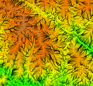
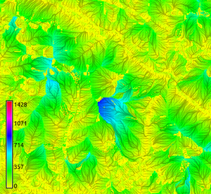
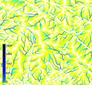
Figure: Flow lines with underlying elevation map; flow lines with underlying flow path lengths (in map units: meters); flow accumulation map (zoomed view)
REFERENCES
- Mitasova, H., L. Mitas, 1993, Interpolation by regularized spline with tension : I. Theory and implementation. Mathematical Geology 25, p. 641-655. (online)
- Mitasova and Hofierka 1993 : Interpolation by Regularized Spline with Tension: II. Application to Terrain Modeling and Surface Geometry Analysis. Mathematical Geology 25(6), 657-669 (online).
- Mitasova, H., Mitas, L., Brown, W.M., Gerdes, D.P., Kosinovsky, I., Baker, T., 1995: Modeling spatially and temporally distributed phenomena: New methods and tools for GRASS GIS. International Journal of Geographical Information Systems 9(4), 433-446.
- Mitasova, H., J. Hofierka, M. Zlocha, L.R. Iverson, 1996, Modeling topographic potential for erosion and deposition using GIS. Int. Journal of Geographical Information Science, 10(5), 629-641. (reply to a comment to this paper appears in 1997 in Int. Journal of Geographical Information Science, Vol. 11, No. 6)
- Mitasova, H.(1993): Surfaces and modeling. Grassclippings (winter and spring) p.18-19.
SEE ALSO
r.basins.fill, r.drain, r.fill.dir, r.water.outlet, r.watershed, v.category, v.to.rastAUTHORS
Original version of program: Maros Zlocha and Jaroslav Hofierka, Comenius University, Bratislava, SlovakiaThe version of the program (adapted for GRASS 5.0): Joshua Caplan, Mark Ruesink, Helena Mitasova, University of Illinois at Urbana-Champaign with support from USA CERL. GMSL/University of Illinois at Urbana-Champaign
SOURCE CODE
Available at: r.flow source code (history)
Latest change: Thursday Feb 03 11:10:06 2022 in commit: 547ff44e6aecfb4c9cbf6a4717fc14e521bec0be
Main index | Raster index | Topics index | Keywords index | Graphical index | Full index
© 2003-2023 GRASS Development Team, GRASS GIS 8.2.2dev Reference Manual