|
Electromagnetic Spectrum:
Transmittance, Absorptance, and Reflectance
|
This page concentrates on what can happen to solar radiation as it passes through the atmosphere and hits objects/materials at the surface of Earth (or any planetary body); typically some of the irradiance is absorbed by the atmosphere and a fraction of the remaining radiation may be absorbed or reflected by surface features, or occasionally a large part is transmitted by penetrating the transparent/translucent features to varying depths (as occurs when light enters water). The effects of specular and diffuse surfaces on the radiometric values measured are examined.
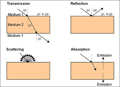
Any beam of photons from some source passing through medium 1 (usually air) that impinge upon an object or target (medium 2) will experience one or more reactions that are summarized in this diagram:
Some objects are capable of transmitting the light through without significant diminution (note how the beam bends twice at the medium 1/medium 2 interface but emerges at the same angle as entry). Other materials cause the light energy to be absorbed (and in part emitted as longer wavelength radiation). Or, the light can be reflected at the same angle as it formed on approach. More commonly the nature of the object's surface (owing to microscopic roughness) causes it to be scattered in all directions.
The primary source of energy that illuminates natural targets is the Sun. Solar irradiation (also called insolation) arrives at Earth at wavelengths which are determined by the photospheric temperature of the sun (peaking near 5600 °C). The main wavelength interval is between 200 and 3400 nm (0.2 and 3.4 µm), with the maximum power input close to 480 nm (0.48 µm), which is in the visible green region. As solar rays arrive at the Earth, the atmosphere absorbs or backscatters a fraction of them and transmits the remainder.
Upon striking the land and ocean surface (and objects thereon), and atmospheric targets, such as air, moisture, and clouds, the incoming radiation (irradiance) partitions into three modes of energy-interaction response:
(1) Transmittance (τ) - some fraction (up to 100%) of the radiation penetrates into certain surface materials such as water and if the material is transparent and thin in one dimension, normally passes through, generally with some diminution.
(2) Absorptance (α) - some radiation is absorbed through electron or molecular reactions within the medium ; a portion of this energy is then re-emitted, usually at longer wavelengths, and some of it remains and heats the target;
(3) Reflectance (ρ) - some radiation (commonly 100%) reflects (moves away from the target) and scatters away from the target at various angles, depending on the surface roughness and the angle of incidence of the rays.
Because they involve ratios
(to irradiance), these three parameters are dimensionless numbers (between 0 and
1), but are commonly expressed as percentages. Following the Law of Conservation
of Energy: τ + α + ρ = 1.
A fourth situation, when
the emitted radiation results from internal atomic/molecular excitation, usually
related to the heat state of a body, is a thermal process. The theory underlying
thermal remote sensing is treated in Section 9. When a remote sensing instrument
has a line-of-sight with an object that is reflecting solar energy, then the
instrument collects that reflected energy and records the observation. Most
remote sensing systems are designed to collect reflected radiation.
I-10 From
the above graph, calculate (approximately) the percent decrease in surface irradiance
(drop in power, in Watts/meter2/µm) of maximum solar radiation (close
to 500 nanometers) from the moment it reaches the outer atmosphere until it
reaches the Earth's surface; assume a vertical rather than slant path through
the atmosphere. ANSWER
There are two general types
of reflecting surfaces that interact with EMR: specular (smooth) and diffuse
(rough). These terms are defined geometrically, not physically. A surface
may appear to be smooth in a physical sense, i.e., it appears and feels smooth,
but at a scale on the order of wavelengths of light, many irregularities might
occur throughout that surface. (A concrete roadway may appear smooth and flat
from a distance but feels rough when a finger passes over it, owing to small grooves,
pits, and protuberances.) Radiation impinging on a diffuse surface tends to be
reflected in many directions (scattered). The Rayleigh criterion is used to determine
surface roughness with respect to radiation:
where h is the surface irregularity
height (measured in Angstroms), λ is the wavelength (also in Angstroms) and
θ is the angle of incidence (measured from the normal [perpendicular] to
the surface. If λ is less than h, the surface acts as a diffuse reflector;
if greater than h, the surface is specular.
A specular surface reflects
radiation according to Snell's Law which states that the angle of incidence θi
is equal to the angle of reflectance θr (where the light ray moves
in the principal plane that passes normal to the surface). Actual values (e.g.,
radiances) of specular reflected radiation depend on the type of material making
up the specular surface. Specular reflectances within the visible wavelength range
vary from as high as 0.99 for a very good mirror to as low as 0.02-0.04 for a
very smooth water surface.
In general, natural surfaces
are almost always diffuse and depart significantly from specular at shorter wavelengths
(into the infrared) and may still be somewhat diffuse in the microwave region.
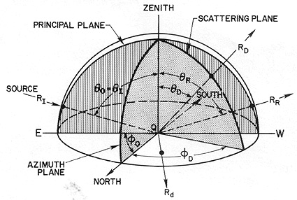
The behavior of a perfectly
diffuse, or Lambertian, surface is described with the help of this figure:
Consider a bundle of rays
(making up the radiation flux) from a single distant source position at an incident
angle θI (relative to the zenith direction) and an azimuth angle
φ0 (relative to north). Imagine the (arbitrarily) horizontal plane
of a target being irradiated to be enclosed in a hemisphere (this simplifies some
calculations because it allows polar coordinates to be used [which we will ignore
here]). For the wavelength conditions we set, the surface is considered rough
or diffuse and has irregularities where the surface departs from horizontal, at
varying slopes. A given ray RI located in the principal plane now strikes
the surface at a point Q1. It will be reflected according to the position
of the minute surface at Q depending on its slope. If that surface is horizontal
(slope = 0°), the ray moves away along path RR in the principal plane
as though this geometry is specular. But if the point surface Qs is
non-horizontal, i.e., has varying slopes defining the shape of the irregularity,
the ray (mathematically treatable as a vector) will now move out along some direction
RD through its scattering plane whose position is defined by θD
and φD. At other points (Qn) on the surface, the direction
of the outgoing R will differ according to the orientation of the slope at the
immediate irregularity. Thus, a large number of incoming rays meeting the surface
at other irregularities (most probably with randomly oriented slopes) will be
redirected (diverge) in all possible directions extending through the hemisphere
of reference.
The radiance in any one direction
is, on average, the same as any other; in other words, radiance is constant at
any viewing position on the hemishpere and is therefore independent of θ0.
However, the radiant intensity at any position will vary according to the relation
Iθ = I0cosθ. This states that as the angle of
incident radiation Iθ is varied, the intensity of outgoing radiation
also changes. For normal incidence (from the zenith), θ is 0 and cosθ
is 1, so Iθ = I0. For all other angles cosθ is
less than 1 and I0 is reduced. Although a homogeneous, non-variant
surface viewed from any position will seem to be uniformly illuminated (constant
radiance), that surface will become less bright as the source is moved from a
vertical (overhead) position towards the plane itself (horizon).
The term bidirectional
reflectance describes the common observational condition in remote sensing
in which the viewing angle φ differs from the angle θ of rays incident
on a diffuse surface, and incoming/outgoing rays are not in the same principal
plane (different azimuths). Thus, reflectances from the same target (type) change
in value from various combinations of θ and φ: this is particularly
important when the sensor operates off-nadir (looking sidewards) and the Sun angle
and azimuth vary during the period of operation (as occur as an aircraft moves
back and forth along paths during an aerial photography mission). Consider this
diagram (treating the two dimenionsal case; in reality the behavior can be displayed
in the third dimension using a hemisphere as reference):
h is less
than or equal to wavelength λ/8cosθ
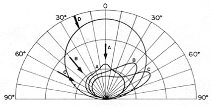
For an imperfectly diffuse reflector (having a specular component) and a viewer directly overhead (such as a sensor looking straight down normal to the Earth's surface), scattering will produce three-dimensional envelopes (shown here as a two-dimensional slice) of reflectances deriving from rays A, B, and C. These radiances vary in intensity in an asymmetric way (except for A). Thus, for B and C rays, there is general diffuse reflectance in all directions plus a "spike" or differential increase in directions spread around the angle of the specular component. Since reflectances also vary with wavelength, envelopes of bidirectional reflectance must be calculated for each wavelength in the range of λs considered.