Scanners, such as those on the Landsats (MSS and TM) were the prime Earth-observing sensors during the 1970s into the 1980s. But these instruments contained moving parts, such as oscillating mirrors that were subject to wear and failure (although remarkably, the MSS on Landsat 5 continues to operate into 1999 after launch in March of 1984). Another approach to sensing EM radiation was developed in the interim, namely the Pushbroom Scanner, which uses charge-coupled devices (CCDs) as the detector. This diagram may help to better grasp the description of CCDs in the next paragraph:
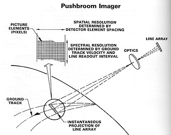
A CCD is an extremely small, silicon chip, which is light-sensitive. When photons strike a CCD, electronic charges develop whose magnitudes are proportional to the intensity of the impinging radiation during a short time interval (exposure time). From 3,000 to more than 10,000 detector elements (the CCDs) can occupy a linear space less than 15 cm in length. The number of elements per unit length, along with the optics, determine the spatial resolution of the instrument. Using integrated circuits each linear array is sampled very rapidly in sequence, producing an electrical signal that varies with the radiation striking the array. This changing signal recording goes through a processor to a recorder, and finally, is used to drive an electro-optical device to make a black and white image, similar to MSS or TM signals. After the instrument samples, the array discharges electronically fast enough to allow the next incoming radiation to be detected independently. A linear (one-dimensional) array acting as the detecting sensor advances with the spacecraft's orbital motion, producing successive lines of image data (analogous to the forward sweep of a pushbroom). Using filters to select wavelength intervals, each associated with a CCD array, we get multiband sensing. The one disadvantage of current CCD systems is their limitation to visible and near IR (VNIR) intervals of the EM spectrum.
CCD detectors are now in common
use on air- and space-borne sensors (including the Hubble Space Telescope which
captures astronomical scenes on a two-dimensional array, i.e., many parallel rows
of detectors). The first airborne pushbroom scanner to be used operationally was
the Multispectral Electro-optical Imaging Scanner (MEIS) built by Canada's CCRS.
It images in 8 bands from 0.39 to 1.1 µm (using optical filters to produce the
narrow band intervals) and uses a mirror to collect fore and aft views (along
track) suitable as stereo imagery.
The German Aerospace Research
Establishment (DFVLR) developed the first pushbroom scanner to be flown in space.
The Modular Optico-electronic Multispectral Scanner (MOMS) was aboard Shuttle
Mission STS-7 and STS-11 in 1983 and 1984. It uses two bands, at 0.575-0.625
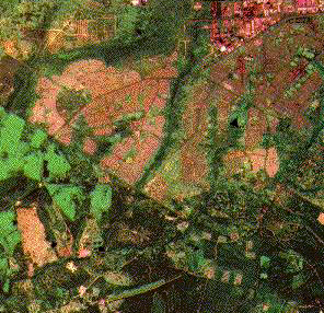
and 0.825-0.975 µm, to produce 20 m resolution images. The MOMS image below
is an area of farmland in Zimbabwe:
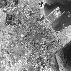
MOMS-2 was flown on STS-55
in May of 1993. It has four multispectral channels (13 m resolution) and a panchromatic
band (4.3 m), and is in stereo mode. Here is a panchromatic image of a city on
the western shore of the Persian Gulf (locus incertae; probably in Qatar):/p>
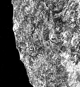
The first use of CCD-based
pushbroom scanners on an unmanned Earth-observing spacecraft was on the French
SPOT-1 launched in 1986. (Page 3-2 describes the
SPOT system, which is operated as a commercial program; 4 SPOTS have now been
launched) An example of a SPOT image, from its high-resolution video (HRV) camera,
covering a 60 km section (at 20 m. spatial resolution) of the coastal region
in southwest Oregon, is the next image we show. Note that scan lines are absent,
because each CCD element is, in effect, a tiny area analogous to a pixel.
False color composites
are a standard product from SPOT. Here is part of a SPOT image taken in 1994
of developing farmland west of Miami, FL and near the edge of the Everglades,
in which a new housing development has been put in since the mid-80s.
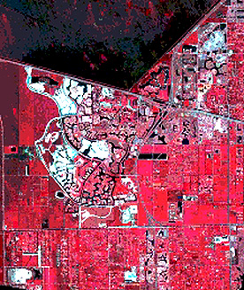
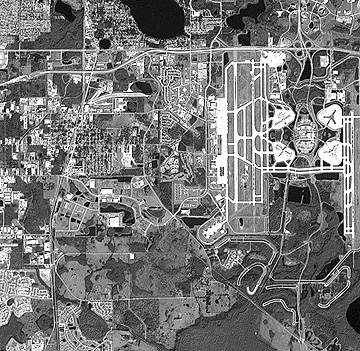
The third image is a panchromatic
image (with 10 meters resolution) showing the edge of Orlando, Florida, including
its airport.