


| Pumps |
A. Introduction
There are many different
kinds of pumps in use around the world. This discussion
is limited to an overview of the most commonly used
pumps.
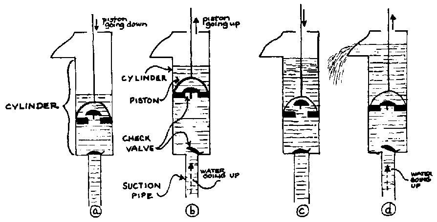
FIG. VII-1. PUMP ACTION
(a) As the piston goes down, the check valve in it opens allowing the water to come through. The check valve at the base of the cylinder remains closed holding the water in the cylinder.
(b) As the piston moves up, the check valve in it closes allowing the water above the piston to be lifted. The rising piston also pulls more water up into the cylinder through the valve at its base.
(c) and (d) The continued down and up motion of the piston inside the cylinder and the opening and closing of the different valves enables water to be moved up and out or the pump.
The most common type of hand pump uses a smooth cylinder against which a piston (plunger) slides up and down. The up and down motion of the piston, coupled with the concurrent action of two valves, causes water to move through the cylinder. (,See Fig. VII-1.)
While there are other types of pumping mechanisms which will be mentioned later, this type of pump is by far the most common.
B. Piston Pump Variations
1. Shallow/deep well pumps
Although the basic operation of cylinder pumps is always the same, there are two different arrangements of the components depending on the distance between the pump and the water surface. For the pump to work the cylinder must be within 6.5 m of the water surface in the well.
Shallow well pump: If the water level in the well is within 6.5 m of where the bottom of where the pump will be placed, the cylinder can be incorporated into the pump body. (See Fig. VII-2.)
Deep well pump: If the water level in the well is more than 6.5 m from the bottom of the pump at any time, the cylinder will have to be inside the well. (See Fig. VII-3.)
Because the working parts of the pump are all above ground in the shallow well pump, this pump is much easier to repair. Deep well pumps, however, are more common because water is not often found within 6.5 m of the ground surface.
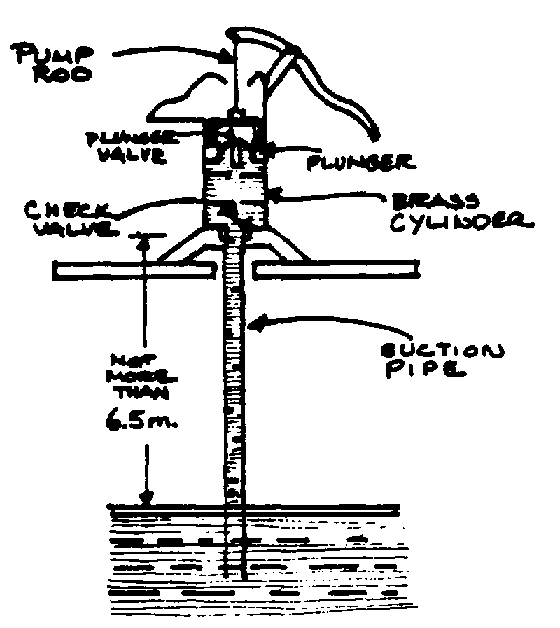
FIG. VII-2. SHALLOW WELL LIFT PUMP
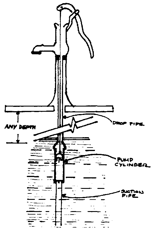
FIG. VII-3. DEEP WELL LIFT PUMP
NOTE: Contrary to popular opinion, pumps do not 'lift' water up from the source. Instead, the pump reduces the atmospheric pressure on the water in the suction pipe and the atmospheric pressure on the water outside of the suction pipe pushes the water up and into the pump. The principle is the same as that of drawing water through a straw or filling a syringe.
Theoretically a pump should be able to raise water 10.4 m up to the cylinder. However, because seals and valves can never function perfectly, the absolute limit is 6.7 meters. Where pumps are locally made tolerances are usually greater so that the practical limit is 6.5 m or even slightly less.
Elevation above sea level also plays a part in determining the practical limit of pumping height because the higher above sea level the less atmospheric pressure there is to push the water up. (See Chart.)
There is no theoretical limit to how far a cylinder can push water up above itself if the pump parts are strong enough. Practically, however, hand pumping over distances greater than about 30 m becomes difficult because of the pressure exerted by the 30 m column of water. To reduce this pressure, most pump manufacturers use progressively smaller cylinders at increasing depths. This reduces the surface area of the piston and therefore the pressure, but it also reduces the output of the pump. In arid hard rock regions where other water lifting techniques are not feasible, hand pumps have been used at depths greater than 50 m.
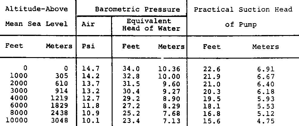
MAXIMUM SUCTION HEAD OF RECIPROCATING HAND PUMPS AT DIFFERENT ALTITUDES FOR WATER AT 60°F (15.6°C)
2. Lift pumps/lift and force pumps
If you plan to use the pump to force the water above the level of the pump spout, you will need a "lift and force" pump. The only difference between this and the simple lift pump is that the lift and force pump has a stuffing box around the pump rod at the top of the pump body to prevent water from flowing out that way. (See Figs. VII-3 and VII-4.)
If you are considering ordering a deep well pump, you will also have to decide whether the pump should have an extractable or non-extractable cylinder. (See Figs. VII-5 and VII-6.)
An open or extractable cylinder is connected to a drop pipe which is slightly larger than the piston assembly in the cylinder. This allows the piston to be removed by simply pulling the pump rod up. The large diameter drop pipe is more expensive, heavier, and more difficult to work with.
A closed or non-extractable cylinder is connected to a smaller diameter drop pipe which will not permit removing the piston assembly by itself. Instead the whole length of pipe must be removed from the well and the cylinder disconnected to permit access to the piston assembly.

FIG. VII-4. SHALLOW WELL; LIFT AND FORCE PUMP

FIG. VII-5. NON-EXTRACTABLE CYLINDER & FIG. VII-6. EXTRACTABLE CYLINDER
The cup seals in the piston assembly need to be changed every three months to three years, depending on how much use the pump gets, the cylinder material, and the quality of the water. In cast iron cylinders the first cup seals tend to wear faster than later seals, perhaps due to an initial honing action. For a closed cylinder changing cup seals will require some kind of heavy lifting device to be able to remove all the pipe and gain access to the cylinder and the piston assembly with its cup seals. The same operation performed on an open cylinder will simply involve disconnecting the pump from the pipe and pulling up the pump rod with the piston assembly attached to its bottom end.
C. Difficulties with Piston Pumps.
All piston pumps present certain difficulties in practical, everyday use.
The cylinder will be seriously damaged if sand is pumped with water. Sand scratches the cylinder wall and wears out the cup seals.
There is the problem of cup seal wear. The smoothness of the cylinder wall largely determines the wear rate of seals. Brass is commonly used because it has a smoother finish than cast iron or steel and will not corrode but cast iron is probably the most commonly used cylinder material. Steel cylinders are rare. Experiments are now underway with plastics and resin cylinders, cylinder liners and cup seals. The initial results are promising.
The pump rod and handle can present problems. Most handle arrangements do not pull the rod straight up and down but allow some lateral movement. This back and forth movement adds to the wear on both the pump rod and the cup seals. For a regular handle arrangement to come close to straight up and down motion, there must be three pivot points which add to the maintenance. However, a new arrangement developed in India, the Jalna-type pump, has one pivot point and pulls the rod straight up and down. (See Fig. VII-7 and VII-8.) The "Mark II" is the latest Indian development in Jalna-type pumps and is being used in UNICEF assisted projects in India and in some African countries.
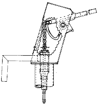
FIG. VII-7. JALNA PUMP HEAD
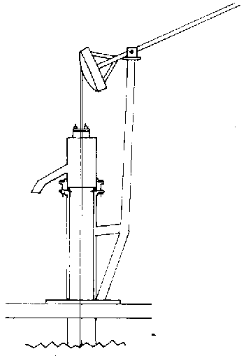
FIG. VII-8. LOCALLY MADE VARIATION OF JALNA PUMP
D. Other Types of Pumps
There are too many other types of water pumps to mention all of them here, but a few should be briefly noted.
1. Diaphragm Pumps
Diaphragm pumps operate similarly to piston pumps with the diaphragm going up and down causing water to move through the pump as two valves alternately open and close. (See Fig. VII9.)
They offer several advantages:
There is no sliding friction of a seal rubbing against a cylinder wall as in a piston pump.
Particles as big as the valve openings can be pumped, with little or no damage to the pump.
A small capacity pump of this type could be easily manufactured by a local machine shop.
There is also one chief disadvantage:
An uneven stress is exerted on the diaphragm causing it to wear more quickly around the piston.
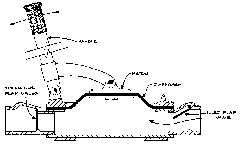
FIG. VII-9. DIAPHRAGM PUMP
2. Helical Rotor Pumps
This is a modern type of pump with a spiral-shaped interior design which is preferred in several developing countries because of the extremely limited amount of maintenance that is required despite the pump's high cost. It will pump almost anything that is capable of being forced through its pumping unit with little or no damage to it.
Two handles are used to drive the gear which turns the shaft with the rotor, on its bottom end, which turns inside a rubber stator to move water upward. (See Fig. VII-10.) The pump is designed in such a way that the weight of the water is supported on a set of bearings, as opposed to piston pumps which support the weight of the water through the pump rod and pump handle. Unlike standard rotary pumps, the height to which water can be pumped with a helical rotor is not determined by the speed of the pump.
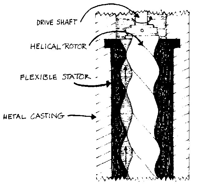
FIG. VII-10. HELICAL ROTOR PUMPING UNIT
3. Bucket pumps
A series of buckets attached to a chain or rope pick up water and dump it into the spout as the handle is turned. This type of pump can be easily made from locally available materials. (See Fig. VII-11.)
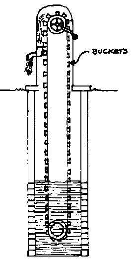
FIG. VII-11. BUCKET PUMP
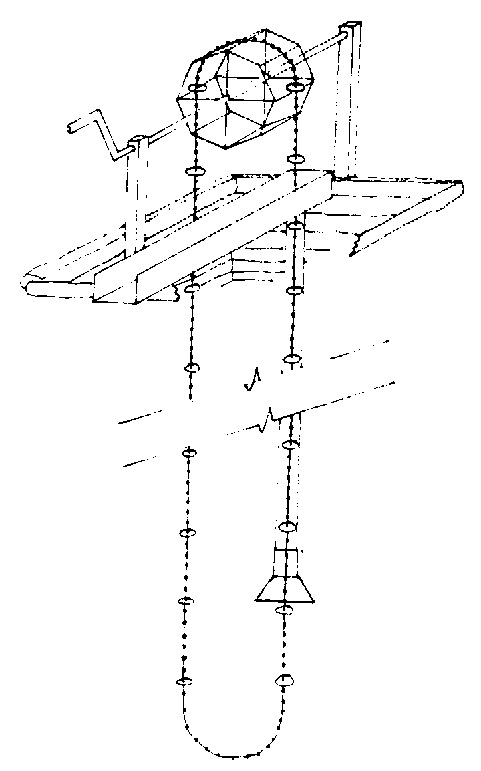
FIG. VII-12. CHAIN PUMP
4. Chain Pumps
Leather or rubber discs usually attached to a chain trap water in the pipe and push it up through the pipe to the spout as the handle is turned to move the chain. This type of pump car. be readily modified to make it suitable for local manufacture. (See Fig. VII12.)
5. Motorized pumps
Motorized pumps are normally not appropriate for rural water supplies where a limited amount of water is needed. The energy required to power these pumps is usually expensive, not readily available or both.
The motorized pumps most commonly used for pumping water are:
Centrifugal pumps which rely on an outside power source to turn a rotor fast enough to both lift and force water. (See Fig. VII-13.)
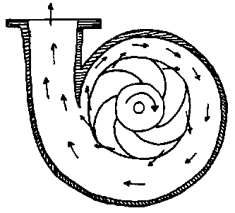
FIG. VII-13. CENTRIFUGAL PUMP
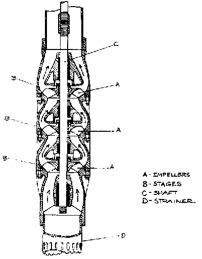
FIG. VII-14. TURBINE PUMP
Turbine pumps which also rely on an outside power source to turn a rotor fast enough to move the water. The turbine rotors must be submerged. (See Fig. VII-14.)
6. Hydraulic Rams
Hydraulic rams cannot be used to lift water from a well, but in the proper situation can be very useful in pumping water from one location to another. Rams are most often utilized to move water from an open body of water above the ram to a storage tank or cistern which is higher than the level of the open body of water.
E. Manufacturing a Pump
Another approach to the installation of pumps which has been successful in some areas is to purchase only that part of the complete pumping unit which needs to be carefully machined. The rest of the pump can be assembled from locally available materials, with the obvious advantages of familiarity and availability.
The most widely used pump of this type is composed of a cylinder assembly,purchased from a manufacturer, attached to locally available galvanized drop pipe. The pump stand, handle and spout can be assembled from wood and pipe. (See Fig. VII-15.)
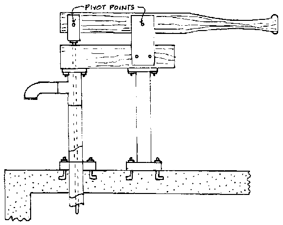
FIG. VII-15. LOCALLY MADE PUMP HEAD

