| Abstract | Top |
Image fusion techniques are useful to integrate the geometric detail of a high-resolution panchromatic (PAN) image and the spectral information of a low-resolution multispectral (MSS) image, particularly important for understanding land use dynamics at larger scale (1:25000 or lower), which is required by the decision makers to adopt holistic approaches for regional planning. Fused images can extract features from source images and provide more information than one scene of MSS image. High spectral resolution aids in identification of objects more distinctly while high spatial resolution allows locating the objects more clearly. The geoinformatics technologies with an ability to provide high-spatial-spectral-resolution data helps in inventorying, mapping, monitoring and sustainable management of natural resources.
Fusion module in GRDSS, taking into consideration the limitations in spatial resolution of MSS data and spectral resolution of PAN data, provide high-spatial-spectral-resolution remote sensing images required for land use mapping on regional scale. GRDSS is a freeware GIS Graphic User Interface (GUI) developed in Tcl/Tk is based on command line arguments of GRASS (Geographic Resources Analysis Support System) with the functionalities for raster analysis, vector analysis, site analysis, image processing, modeling and graphics visualization. It has the capabilities to capture, store, process, analyse, prioritize and display spatial and temporal data.
Keywords: Image fusion, GIS, Remote Sensing, GRDSS, GRASS, Geoinformatics
| 1. Introduction | Top |
Image fusion is a process of creating images with better spatial and spectral resolution by merging two or more images of different spatial and spectral resolution. This would be useful in earth resources inventorying, mapping and monitoring. Fusion is possible, as most of the latest earth observation satellites provide both high-resolution panchromatic and low-resolution multispectral images (Yun Zhang et al., 2004). It is possible to have several images of the same scene providing different information although the scene is the same. This is because each image has been captured with a different sensor. If we are able to merge the different information to obtain to obtain a new and improved image, we have a fused image and the method is called a fusion scheme (Gonzalo Pajares et al., 2004). High spectral resolution allows identification of materials in the scene, while high spatial resolution locates those materials (Harry N. Gross et al., 1998). It can extract features from source image, and provide more information than one image can. Multi-resolution analysis plays an important role in image processing, it provides a technique to decompose an image and extract information from coarse to fine scales (C.Y.Wen et al., 2004). Image fusion basically refers to the acquisition, processing and synergistic combination of information provided by various sensors or by the same sensor in many measuring contexts (G. Simone, 2001).
The objective of image fusion is to combine information from multiple images of the same scene. The result of image fusion is a new image which is more suitable for human and machine perception or further image processing tasks such as segmentation, feature extraction and object recognition (Gonzalo Pajares et al., 2004). Image fusion improves the interpretability of satellite images. Image data obtained from different types of sensors provide complementary information about a scene. Data fusion helps us to extract maximum information from the data set in such a way as to achieve optimal resolution in the spatial and spectral domain. The detection and the recognition of objects in the scene will be done with minimum error probability where the redundant information will improve reliability, and the complementary information will improve capability. Image fusion also aims at the integration of disparate and complementary data to enhance the information apparent in the image as well as to increase the reliability of the interpretation leading to more accurate data and utility (Sanjeevi, S.). An effective way to improve the accuracy of the classification of multitemporal remote-sensing images is represented by the fusion of spectral information with spatial and temporal contextual information (Farid Melgani et al., 2002). The resultant image obtained from fusion technique has the advantage of spatial detail, the spectral detail, and the topographical detail derived from different sources could be maximized by a data fusion technique (NASA, 2003). The low and high resolution images must be geometrically registered prior to fusion. The higher resolution image is used as the reference to which the lower resolution image is registered. Effective multisensor image fusion also requires radiometric correlation between two images, i.e. they must have some reasonable degree of similarity. Artifacts in fused images arise from poor spectral correlation.
In the detail study of land surface phenomena high spatial resolution multispectral image data are indispensable (Y. Oguru et al ., 2001). For example in urban area, many land cover types/surface material are spectrally similar. This makes it extremely difficult to analyze an urban scene using a single sensor with a limited spectral range (Forster, 1985; Hepner et al., 1998). Some of the land cover types are spectrally indistinguishable from each other within a Landsat TM scene, such as water or shadow, trees and shrubs vs. lawns, and bare soil vs. newly completed concrete sections (Wheeler, 1995). Data fusion is capable of integrating different imagery data creating more information than can be derived from a single sensor (C-M Chen et al., 2003).
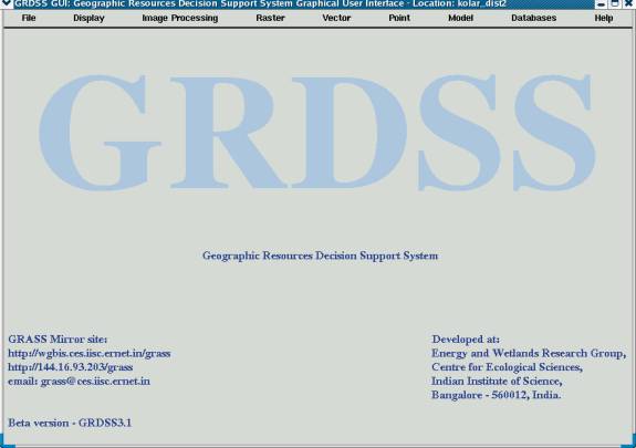
In this regard Open Source GIS such as GRASS (Geographic Resources Analysis Support System, http://wgbis.ces.iisc.ac.in/grass/welcome.html) helps in land cover and land use analysis in a cost-effective way. Most of the commands in GRASS are command line arguments and requires a user friendly and cost-effective graphical user interface (GUI). GRDSS (Geographic Resources Decision Support System) has been developed in this regard to help the users. It has functionality such as raster, topological vector, image processing, graphics production, etc. (Ramachandra T.V., Uttam Kumar et al., 2004). Figure 1 depicts the Main menu of GRDSS. It operates through a GUI developed in Tcl/Tk under LINUX. GRDSS include options such as Import / Export (of different data formats), extraction of individual bands from the IRS (Indian Remote Sensing Satellites) data (in Band Interleaved by Lines format), display, digital image processing, map editing, raster analysis, vector analysis, point analysis, spatial query, etc. These are required for regional resource mapping, inventorying and analysis such as Land cover and Land use Analysis, Watershed Analysis, Landscape Analysis, etc.

Figure 1: GRDSS
The objective of this endeavor is to carry out the land cover/land use and temporal change analysis using fused images for Kolar district, Karnataka State, India using GRDSS (Geographic Resources Decision Support System).
| 2. Image fusion techniques and the existing fusion modules in GRDSS | Top |
Image fusion is performed at the three different processing levels according to the stages at which the fusion takes place: pixel, feature and decision level. To date, many image fusion techniques have been developed. Many scientific papers on image fusion have been published with the emphasis on improving fusion quality and reducing colour distortion. However, the available algorithm can hardly produce satisfactory fusion result. The new innovations in the Geoinformatics Technology entails many fusion algorithm such as IHS (Intensity, Hue, Saturation), PCA (Principal Components Analysis), Arithmetic Combinations (the Brovey transformation with a simple computation to image fusion), Wavelet base fusion, Minimum Noise Fraction (MNF) transformation etc. The IHS technique is the most widely used one (Prinz et al., 1997, Yun Zhang et al ., 2004). A brief overview of the methods gives the description of each technique as discussed below.
2.1. IHS fusion technique
The IHS fusion converts a colour image from the RGB (Red, Green, Blue) space into the IHS (Intensity, Hue, Saturation) colour space. Because the Intensity (I) band resembles a PAN image. It is replaced by a high-resolution Pan image in the fusion. A reverse IHS transform is then performed on the PAN together with the Hue (H) and Saturation (S) bands, resulting in an IHS fused image (Yun Zhang, 2004).
The general IHS procedure uses three bands of a lower spatial resolution dataset and transforms these data to IHS space. A contrast stretch is then applied to the higher spatial resolution image so that the stretched image has approximately the same variance and average as the intensity component image. Then, the stretched, higher resolution image replaces the intensity component before the image is transformed back into the original colour space (Chavez et al., 1991). The IHS colour coordinate system is based on a hypothetical colour sphere. The vertical axis represents intensity, which ranges from 0 (black) to 255 (white). The circumference of the sphere represents hue, which is the dominant wavelength of colour. Hue ranges from 0 to at the midpoint of red tones through green, blue and black to 255, adjacent to 0. Saturation represents the purity of the colour and ranges from 0 as the center of the colour sphere to 255 at the circumference (Jensen, 1996). The IHS values can be derived from the RGB values through transformation equations. The following equations (equation 1, 2, and 3) are used to compute IHS values for a RGB image (BV1, BV2 and BV3). The IHS values can also be converted back into RGB values using the inverse equations (Pellemans et al ., 1993).
I = (BV1+BV2+BV3)/3 ----------------- (1)
H = [arctan (2BV1-BV2-BV3) / √ 3(BV2 BV3)] + C ----------------- (2)
S = √ 6(BV12 + BV22 +BV32 BV 1 BV 2 BV 1 BV 3 BV 2 BV 3 ) -0.5 / 3 ------------------ (3)
where, C = 0, if BV 2 >= BV 3 ; C = Π , if BV 2 < BV 3 .
IHS transformation can enhance image features, improve spatial resolution, and integrate disparate data at low processing cost. Other colour related techniques such as colour composites (RGB) and luminance- chrominance (YIQ) do not have all these advantages (Pohl and van Genderen, 1998).
Some variation to IHS transformation is available as:
(HSI Transformation)
I = max{R,G,B}
(a) In case of I =0, S=0, H=undefined.
(b) In case of I ? 0, S = (I-i)/I where i = min{R,G,B},
r = (I-R)/(I-i), g= (I-G)/(I-i), b=(I-B)/(I-i),
In case of R=I, H= (b-g) * p/3
In case of G=I, H= (2+r+b) * p /3
In case of B=I, H= (4+g+r) * p /3
In case of H<0, H=H+2 * p
Where, max {} is given the function that compares signed integers and returns the largest of them. And min {} is the function that compares signed integers and returns the least of them. (Y. Oguru et al ., 2003)
(Inverse HSI Transformation)
• In case of S = 0, R=G=B=I
• In case of S ?0, h=floor( 3 * h/ p ), if H=2* p then
H =0, P=I * (1-S), Q=I * {1-S * (H-h)}, T=I * {1-S * (1-H+h)}
In case of h = 0, R=I, G=T, B=P,
In case of h = 1, R=Q, G=I, B=P,
In case of h = 2, R=P, G=I, B=T,
In case of h = 3, R=P, G=Q, B=I,
In case of h = 4, R=T, G=P, B=I,
In case of h = 5, R=I, G=P, B=Q.
where, floor(x) is the function that computes the largest integral value not greater the x. In case of IRS-LISS3, band 1=G, band 2=R, band 3=NIR. The HSI transformation is performed. The intensity (I) component is replaced by the corresponding panchromatic band and then the inverse HSI transformation is applied (Y. Oguru et al ., 2003).
i.rgb.his It is an image processing program in GRDSS that transforms Red-green-blue (rgb) to hue-intensity-saturation (his) raster map. It processes three input raster map layers as red, green, and blue components and produces three output raster map layers representing the hue, intensity, and saturation of the data. Each output raster map layer is given a linear gray scale color table (figure 2).
i.his.rgb It is an image processing program in GRDSS that processes three input raster map layers as hue, intensity and saturation components and produces three output raster map layers representing the red, green and blue components of this data. The output raster map layers are created by a standard hue-intensity-saturation (his) to red-green-blue (rgb) color transformation (figure 2). Each output raster map layer is given a linear gray scale color. It is not possible to process three bands with i.his.rgb and then exactly recover the original bands with i.rgb.his . This is due to loss of precision because of integer computations and rounding. Tests have shown that more than 70% of the original cell values will be reproduced exactly after transformation in both directions and that 99% will be within plus or minus 1. A few cell values may differ significantly from their original values (source:http://wgbis.ces.iisc.ac.in/grass/gdp/html_grass5/html/i.his.rgb.html).
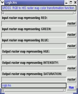
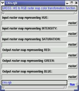
Figure 2: GRDSS module for RGB to HIS and HIS to RGB transformation.
hsv.rgb.sh It is a GRDSS shell script that converts HSV (hue, saturation, and value) cell values to RGB (red, green, and blue) values using r.mapcalc (A GRDSS module for map calculator) . The Foley and Van Dam algorithm is the basis for this program. Input must be three raster files - each file supplying the HSV values. Three new raster files are created representing RGB. (For example, hsv.rgb.sh file1 file2 file3 file4 file5 file6 where file1 file2 file3 are the three input files and file4 file5 file6 are the three output files.)
rgb.hsv.sh It is a Bourne shell program in GRDSS that converts RGB (red, green, and blue) cell values to HSV (hue, saturation, value) values using r.mapcalc (A GRDSS module for map calculator) based on the Foley and Van Dam algorithm. Input must be three raster files - each file supplying the RGB values. Three new raster files are created representing HSV (source:http://wgbis.ces.iisc.ac.in/grass).
2.2. The PCA (Principal Component Analysis )
PCA transformation converts interconnected MSS bands into a new set of uncorrelated components. The first component also resembles a Pan image. It is, therefore, replaced by a high resolution Pan for the fusion. The Pan image is fused into the low-resolution MSS bands by performing a reverse PCA transformation (Yun Zhang, 2004).
Extensive interband correlation is a problem frequently encountered in the analysis of multispectral image data. That is, images generated by digital data from various wavelength bands often appear similar and convey essentially the same information. Principal and Canonical component transformations are two techniques designed to reduce such redundancy in multispectral data. These transformation may be applied either as an enhancement operation prior to visual interpretation of the data or as a preprocessing procedure prior to automated classification process of the data. If employed in the latter context, the transformation generally increase the computational efficiency of the classification process because both principal and canonical component analyses may result in a reduction in the dimensionality of the original data set. Stated differently, the purpose of these procedures is to compress all of the information contained in an original n-band data set into fewer than n new bands or components. The components are then used in lieu of the original data.
Let there be two bands A and B. Let us superimpose two new axes (axes I and II) on the scatter plot of the two bands, that are rotated with respect to the original measurement axes and that have their origin at the mean of the data distribution. Axis I defines the direction of the first principal component and axis II defines the direction of the second principal component. The form of the relationship necessary to transform a data value in the original band-A and B coordinate system into its value in the new axis I - axis II system is given by equation 4 and 5.
DNI = a11 DNA + a 12 DNB ------------------ (4)
DNII = a 21 DNA + a 22 DNB ------------------ (5) where,
DNI , DNII = digital numbers in new (principal component) coordinate system
DNA , DNB = digital number in old coordinate system
a11 , a 12 , a 21 , a 22 = coefficient (constants) for the transformation.
The principal component data values are simply linear combinations of the original data values. One of the characteristics of the PCA for channels of multispectral data is that the first principal component (PC1) includes the largest percentage of the total scene variance and succeeding components (PC2, PC3, , PCn) each contain a decreasing percentage of the scene variance. Principal component enhancements are generated by displaying contrast stretched images of the transformed pixel values. Principal component enhancement techniques are particularly appropriate where little prior information concerning a scene is available. Canonical component analysis, also referred to as multiple discriminant analysis is more appropriate when information about particular features of interest is known. Canonical components not only improve classification efficiency but also can improve classification accuracy for the identified features due to the increased spectral separability of classes (Lillesand and Kiefer, 2000).
i.pca It is the Principal components analysis (PCA) program for image processing in GRDSS based on the algorithm provided by Vali (1990) (http://wgbis.ces.iisc.ac.in/grass/gdp/html_grass4/html/i.pca.html), that processes n (2 >= n) input raster map layers and produces n output raster map layers containing the principal components of the input data in decreasing order of variance ("contrast"). The output raster map layers are assigned names with .1, .2,.....n suffixes (figure 3). The current geographic region definition and mask settings are preserved when reading the input raster map layers. When the rescale option is used, the output files are rescaled to fit the min, max (0,255) range.
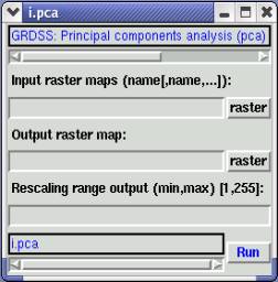
Figure 3: Principal Component Analysis module in GRDSS
i.fft It is a Fast Fourier Transform (FFT) program for image processing in GRDSS based on the FFT algorithm given by Frigo et al. (1998, http://wgbis.ces.iisc.ac.in/grass/gdp/html_grass5/html/i.fft.html) that processes a single input raster map layer and constructs the real and imaginary Fourier components in frequency space (figure 4). In these raster map layers the low frequency components are in the center and the high frequency components are toward the edges. The input_image need not be square; before processing, the X and Y dimensions of the input_image are padded with zeroes to the next highest power of two in extent (i.e., 256 x 256 is processed at that size, but 200 x 400 is padded to 256 x 512). The cell category values for viewing, etc., are calculated by taking the natural log of the actual values then rescaling to 255, or whatever optional range is given by the user, as suggested by Richards (1986). A color table is assigned to the resultant map layer.
i.ifft - Inverse Fast Fourier Transform (IFFT) is an image processing program based on the algorithm given by Frigo et al. (1998, http://wgbis.ces.iisc.ac.in/grass/ gdp/html_grass5/html/i.fft.html), that converts real and imaginary frequency space images (produced by i.fft ) into a normal image (figure 4). The reconstructed image will preserve the cell value scaling of the original image processed by i.fft .
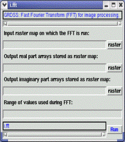
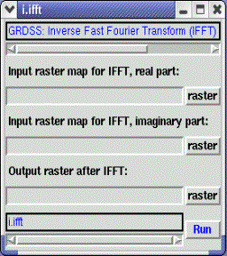
Figure 4: Fast fourier transformation (FFT) and inverse FFT module in GRDSS
i.cca It is an image processing program in GRDSS for computing the Canonical components analysis (cca) as shown in figure 5. It takes from two to eight (raster) band files and a signature file, and outputs the same number of raster band files transformed to provide maximum separability of the categories indicated by the signatures. This implementation of the canonical components transformation is based on the algorithm contained in the LAS image processing system. CCA is also known as "Canonical components transformation".
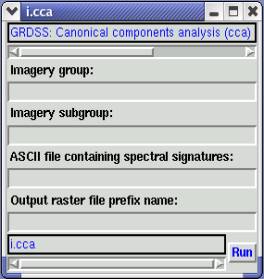
Figure 5: Canonical Component Analysis (CCA) module in GRDSS
r.covar It is a raster based program in GRDSS that outputs a covariance/correlation matrix for user-specified raster map layer(s) as depicted in figure 6. The output is an N x N symmetric covariance (correlation) matrix, where N is the number of raster map layers specified on the command line. This module can be used as the first step of a principle components transformation (PCA). The covariance matrix would be input into a system which determines eigen values and eigen vectors.
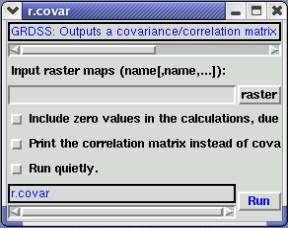
Figure 6: Covariance module
m.eigensystem It is raster program that computes eigen values and eigen vectors for square matricies which can be an input to perform principle component (PCA) transformation on GRDSS data layers.
2.3 Arithmetic combinations
The are numerous possibilities of combining the data using multiplication, ratios, summation or subtraction.
r.mapcalc It is a GRDSS raster map layer calculator (figure 7) that performs arithmetic on raster map. Raster map layers can be created, which are arithmetic expressions involving existing raster map layers, integer or floating point constants, and functions.
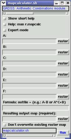
Figure 7: Arithmetic combination module in GRDSS
Different arithmetic combinations have been developed for image fusion. The Brovey Transform, SVR (Synthetic Variable Ratio), and RE (Ratio Enhancement) techniques are some successful examples. The basic procedure of the Brovey Transform first multiplies each MSS band by the high-resolution Pan band, and then divides each product by the sum of the MSS bands. THE SVR and RE techniques are similar, but involve more sophisticated calculations for the MSS sum for better quality. Out of the three methods listed above, the Brovey Transform is discussed below.
2.3.1. The Brovey Transformation
The Brovey transform is a special combination of arithmetic combinations including ratios, is a formula that normalizes multi spectral bands used for an RGB display, and muiltiplies the result by any other resolution image to add the intensity or brightness component to the image. The Brovey transformation (Prinz et al., 1997) is defined by the simple computation given by equation (6). This method assumes that the spectral range spanned by the panchromatic band is same as that covered by the multispectral bands.
Yk(i,j) = X k (i,j) * X p (m, n) / ? 4k=2 Xk (i , j ) ----------------(6)
where, i and j are the pixel number and the line number of k-th multispectral bands respectively. Xk (i,j) is the k-th original multispectral band data. On the other hand, m and n are the pixel number and the line number of panchromatic band data respectively. Xp (m,n) is the original panchromatic band data which exists in a range of the k-th original multispectral band data of Xk (i,j). For example, in case of Landsat -7 ETM+ spectral radiance data, the image fusion by Brovey transformation is to chose the bands 2,3 and 4, resample them to 15 metres spatial resolution and perform the Brovey transformation for the resample image data (Y. Oguru et al ., 2003).
i.fusion.brovey It is one of the image fusion programs in GRDSS that performs a Brovey transformation on three multispectral and a panchromatic satellite image channels to merge multispectral and high-resolution panchromatic channels. The command changes temporarily to the high resolution of the panchromatic channels for creating the three output channels, then restores the previous region settings. The current region coordinates are preserved during transformation.
2.4. Wavelet fusion
The Wavelet transform or Wavelet analysis is probably the most recent solution to overcome the shortcomings of the Fourier transform that expresses a signal as the sum of a, possibly infinite, series of sines and cosines. The disadvantage of Fourier expansion however is that it has only frequency resolution and no time resolution (Sanjeevi, S.). A wavelet is a simple function that, unlike Fourier transform, not only has frequency associated with it, but also scale. The continuous wavelet transform (CWT) is given by equation 7.
?(s,t) = ?f(t)?s. * (t) dt ---------------- (7)
where, * denoted complex conjugation. This equation shows how a function f(t) is decomposed into a set of basis functions ?s, called the wavelet. The variable s (scale) and t (translation) are the new dimension after the wavelet transform. The inverse wavelet transform is represented by equation 8.
f(t ) = ?? ?(s, t) ?s. (t)d tds ---------------- (8)
The wavelets are generated from a single basic wavelet ?(t ) , the so-called mother wavelet, by scaling and translation according to equation 9 where s is the scale factor, t is the translation factor and s-1/2 is for energy normalization across the different scales.
?s (t) = s-1/2 ? [(t-t)/s] ---------------- (9)
The first step consists in extracting the structures present between the images of two different resolutions. These structures are isolated into three wavelet coefficient which corresponds to the detail image according to the three directions (vertical, horizontal and diagonal). Thus in combining the high spatial resolution panchromatic image and low resolution multispectral image, the PAN image is first reference stretched three times, each time to match one of the multispectral band histogram. The first level of the wavelet transform is computed for each of these modified pan images. A synthetic level 1 multispectral wavelet decomposition is constructed using each original multispectral image and the three high frequency components (LxHy, LxHy, HxHy) from the corresponding modified PAN image. In the wavelet decomposition, four components are calculated from different possible combinations of row and column filtering. These components have low resolution because of down-sampling in wavelet transform.
The second step introduces these details into each multispectral band through the inverse wavelet transform. Thus at high resolution, simulated images are produced. The spectral information content of original multi-spectral images is preserved because only the scale structures between the two different resolution images are added (Sanjeevi, S.) .
In short, in wavelet fusion a high-resolution Pan image is first decomposed into a set of low-resolution Pan image with corresponding wavelet coefficients (spatial details) for each level. Individual bands of the MSS image then replace the low-resolution Pan at the resolution level of the original MSS image. The high-resolution spatial detail is put into each MSS band by performing a reverse wavelet transform on each MSS band together with the corresponding wavelet coefficients (Yun Zhang, 2004).
The wavelet based approach is appropriate for performing fusion tasks for the following reasons.
The key step in image fusion based on wavelets is that of coefficient combinations, namely, the process of merging the coefficient in an appropriate way in order to obtain the best quality in the fused image. This can be achieved by a set of strategies. The most simple is to take the average of the coefficient to be merged, but there are other merging strategies with better performances (Gonzalo Pajares et al., 2004). It was an attempt providing guidelines about the use of wavelets in image fusion. The paper has some representative examples that can be extended for performing the wavelet based fusion for any new application. It also provides theory for wavelet fusion approaches. Although the paper is a pixel-level-based approach, it can be easily extended to the other three fusion level schemes (signal, feature and symbol). Nevertheless, special processing should be required such as edge/region detection or object recognition.
A wave equation based imaging techniques using parallel computing (Sudhakar et al., CDAC, Pune) is represented by the mathematical formulation of extrapolation equation for ?-x migration. The paper is based on the Wave Equation Based Imaging Techniques and the explosion power of computers, where high resolution processing amounts to an increase in the computational efforts. Wave equation based methods are now widely recognized and used providing finer detailed geological features then the conventional methods. The discussed ?-x depth migration method images the earths subsurface very well even when there are lateral velocity variations. When continental margin boundary delineation is needed, where there may exist sharp lateral velocity variations, the method can be used for high resolution imaging. Parallel implementation carried out on PARAM 10000 Supercomputers using PVM (Parallel Virtual Machine) & MPI (Message Passing Interface) message passing libraries. Use of PVM/MPI enables the portability of the software across various parallel machines.
2.5. Minimum noise fraction (MNF) transformation
The MNF transformation is mainly used to reduce the data dimensionally of AVIRIS data before performing the data fusion. It was first developed as an alternative to PCA for the Air born Thematic Mapper (ATM) 10-band sensor (Green et al., 1998). It is defined as a two-step cascaded PCA (Research Systems Inc., 1998). The first step, based on an estimated noise covariance matrix, is to decorrelate and rescale the data noise, where the noise has unit variance and no band-to-band correlations. The next step is a standard PCA of the noise-whitened data.
The MNF transformation was derived as an analogue of the PCA and has all the properties of the PCA, including the primary characteristic of the PCA, optimally concentrating the information content of the data in as small number of components as possible (Lee et al., 1990). This transformation is equivalent to principal components when the noise variance is the same in all bands (Green et al ., 1998). By applying the MNF to the geophysical and Environment Research (GER) 64-band data, the results demonstrated the effectiveness of this transformation for noise adjustment in both the spatial and spectral domains (Lee et al., 1990).
Although PCA can efficiently compress hyperspectral data into a few components, this high concentration of total covariance only in the few first components inevitably results from part of the noise variance (Green et al., 1988; Lee et al., 1990; Chen, 2000). The special capability image quality with increasing component number cannot be accomplished easily using other techniques, such as PCA and factor analysis.
| 3. Study area | Top |
Burgeoning population coupled with lack of holistic approaches in planning process has contributed to a major environmental impact in dry arid regions of Karnataka. The Kolar district in Karnataka State, India was chosen for this study. It is located in the southern plain regions (semi arid agro-climatic zone) extending over an area of 8238.47 sq. km. between 77°21' to 78°35' E and 12°46' to 13°58' N (shown in figure 8).
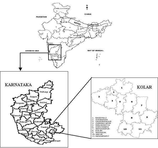
Figure 8: Study area Kolar district, Karnataka State, India
The Kolar district forms part of northern extremity of the Bangalore plateau and since it lies off the coast, it does not enjoy the full benefit of northeast monsoon and being cut off by the high Western Ghats. The rainfall from the southwest monsoon is also prevented, depriving of both the monsoons and subjected to recurring drought. The rainfall is not only scanty but also erratic in nature. The district is devoid of significant perennial surface water resources. The ground water potential is also assessed to be limited. The terrain has a high runoff due to less vegetation cover contributing to erosion of top productive soil layer leading to poor crop yield. Out of about 280 thousand hectares of land under cultivation, 35% is under well and tank irrigation (http://wgbis.ces.iisc.ac.in/energy/ paper/).
The main sources of primary data were from field (using GPS), the Survey of India (SOI) toposheets of 1:50,000, 1:250,000 scale and multispectral sensors (MSS) data of the IRS (Indian Remote Sensing satellites) -1C and IRS -1D (1998 and 2002). LISS-III MSS data scenes corresponding to the district for path-rows (100, 63) (100, 64) and (101, 64) was procured from the National Remote Sensing Agency, Hyderabad, India (http://www.nrsa.gov.in). The secondary data was collected from the government agencies (Directorate of census operations, Agriculture department, Forest department and Horticulture department).
| 4. Methodology | Top |
The methodology of the study involved:-
| 5. Results and Discussion | Top |
Land cover analysis was done by computing Normalized Difference Vegetation Index (NDVI) which shows 46.03 % area under vegetation and 53.98 % area under non-vegetation. Vegetation index differencing technique was used to analyze the amount of change in vegetation (green) versus non-vegetation (non-green) with the two temporal data. NDVI is based on the principle of spectral difference based on strong vegetation absorbance in the red and strong reflectance in the near-infrared part of the spectrum.
D NDVI = (IR-R)/(IR+R) t2 (IR-R)/(IR+R) t1 ---------------------(10)
where, t1 and t2 denote the two different dates, t1 (1998) and t2 (2002).
The result shows a 16.46 % difference in the vegetation area between the two dates. Figure 9 depicts the image obtained from Vegetation Index Differencing between the two dates (1998 and 2002).
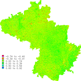
Figure 9: Vegetation Index Differencing
Land use analysis was done using supervised classification approach (accuracy 78.08 %) using Gaussian Maximum Likelihood Classifier (GMLC) in to five categories (agriculture, built-up, forest, plantation and waste land) as depicted in figure 10.
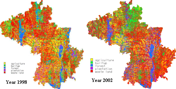
Figure 10: Classified image
The Land use analyses as given in Table 1, indicates increase of non-vegetation area from 451752 ha. (54.84% in 1998) to 495238 ha (60.17% in 2002). The results also show decrement in forest area and increment in builtup (18.79 %), plantation (12.53 %) and waste land (41.38 %) in 2002 against that in 1998 (builtup-15.96%, plantation-8.53% and waste land-38.88%). Further, taluk wise land use data was extracted by overlaying taluk boundaries and results are tabulated in Table 2.
1998 |
2002 |
|||
Categories |
Area (in ha) |
Area (%) |
Area (in ha) |
Area (%) |
Agriculture |
233519 |
28.34 |
165711.42 |
20.13 |
Builtup |
131468 |
15.96 |
154668.68 |
18.79 |
Forest |
68300 |
8.29 |
58979.35 |
7.17 |
Plantation |
70276 |
8.53 |
103110.13 |
12.53 |
Waste land |
320284 |
38.88 |
340570.16 |
41.38 |
Table 1: Land use details of Kolar district
Taluk |
Agriculture (%) |
Built up (%) |
Forest(%) |
Plantation(%) |
Waste land (%) |
|||||
1998 |
2002 |
1998 |
2002 |
1998 |
2002 |
1998 |
2002 |
1998 |
2002 |
|
Bagepalli |
15.75 |
12.69 |
22.46 |
44.65 |
09.26 |
03.28 |
03.65 |
07.51 |
48.88 |
31.86 |
Bangarpet |
27.43 |
14.15 |
15.83 |
09.65 |
15.95 |
12.59 |
13.97 |
13.32 |
26.82 |
50.28 |
Chikballapur |
30.61 |
30.28 |
10.56 |
13.59 |
18.30 |
13.35 |
08.16 |
15.18 |
32.37 |
27.60 |
Chintamani |
29.94 |
20.07 |
13.59 |
20.11 |
01.95 |
01.61 |
05.52 |
08.52 |
49.00 |
49.69 |
Gauribidanur |
22.75 |
17.24 |
22.11 |
23.97 |
06.50 |
04.12 |
02.61 |
11.57 |
46.03 |
43.10 |
Gudibanda |
15.58 |
22.71 |
11.04 |
19.69 |
04.47 |
04.67 |
02.55 |
09.42 |
66.36 |
43.52 |
Kolar |
33.47 |
21.81 |
13.09 |
12.93 |
05.70 |
08.62 |
07.67 |
14.25 |
40.07 |
42.40 |
Malur |
40.95 |
22.56 |
08.52 |
12.84 |
03.03 |
09.05 |
19.62 |
17.12 |
27.88 |
38.42 |
Mulbagal |
22.85 |
19.26 |
21.13 |
12.72 |
06.25 |
01.98 |
09.35 |
06.58 |
40.42 |
59.46 |
Sidlaghatta |
32.47 |
24.72 |
13.95 |
24.76 |
03.27 |
07.61 |
10.75 |
15.92 |
39.56 |
26.98 |
Srinivaspur |
36.52 |
22.93 |
15.34 |
08.04 |
13.65 |
12.67 |
09.34 |
19.10 |
25.15 |
37.25 |
District |
28.35 |
20.13 |
15.96 |
18.79 |
08.29 |
07.17 |
08.53 |
12.53 |
38.87 |
41.38 |
Table 2: Taluk wise land use in percentage area (1998 and 2002)
LISS3 multispectral (MSS) data of the IRS 1C and 1D of resolution-23.5 meters (both 1998 and 2002) were merged with the PAN data of IRS 1C resolution-5.8 meters using the IHS fusion technique for better spatial and spectral resolutions. Supervised classifications were performed for selected taluks with ground truth data. Figure 11 gives the classified image for Chikballapur taluk. The comparative results of the taluks where subtle change detection could be observed in 2002 are as listed in Table 3 and the corresponding taluk wise area in percentage are as listed in Table 4.
Taluk |
Agriculture |
Built up |
Forest |
Plantation |
Waste land |
Chikballapur |
19220.54 |
9293.13 |
7143.66 |
9099.19 |
19064.50 |
Chintamani |
19958.61 |
19957.48 |
1488.25 |
7358.55 |
40140.64 |
Gauribidanur |
15612.86 |
19447.85 |
3310.56 |
10929.94 |
39557.35 |
Gudibanda |
5080.74 |
4662.85 |
846.32 |
2738.80 |
9398.59 |
Mulbagal |
13251.53 |
10034.88 |
2578.21 |
4940.57 |
51168.42 |
Sidlaghatta |
15872.94 |
13614.46 |
5145.42 |
12425.18 |
19999.06 |
Srinivaspur |
20189.23 |
7650.96 |
11006.07 |
15490.01 |
31942.53 |
Table 3: Talukwise land use area in hectares (ha) of the year 2002
Taluk |
Agriculture (%) |
Built up (%) |
Forest(%) |
Plantation(%) |
Waste land (%) |
|||||
1998 |
2002 |
1998 |
2002 |
1998 |
2002 |
1998 |
2002 |
1998 |
2002 |
|
Chikballapur |
32.08 |
30.12 |
08.57 |
14.56 |
17.55 |
11.19 |
10.97 |
14.26 |
30.82 |
29.87 |
Chintamani |
23.45 |
22.45 |
12.90 |
22.45 |
04.22 |
01.67 |
08.13 |
8.28 |
51.00 |
45.15 |
Gauribidanur |
25.46 |
17.57 |
21.43 |
21.89 |
07.98 |
03.73 |
02.77 |
12.30 |
42.36 |
44.52 |
Gudibanda |
16.71 |
22.36 |
12.63 |
20.52 |
05.25 |
03.72 |
03.29 |
12.05 |
62.12 |
41.35 |
Mulbagal |
23.23 |
16.17 |
20.68 |
12.24 |
06.59 |
03.15 |
09.37 |
06.03 |
40.13 |
62.42 |
Sidlaghatta |
30.94 |
23.67 |
15.18 |
20.30 |
03.12 |
07.67 |
09.94 |
18.53 |
40.83 |
29.82 |
Srinivaspur |
33.39 |
23.40 |
17.97 |
08.87 |
10.29 |
12.76 |
09.70 |
17.95 |
28.64 |
37.02 |
Table 4: Taluk wise land use in percentage area (1998 and 2002)
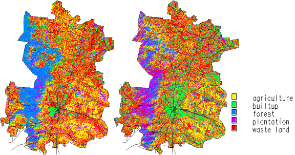
Figure 11: Classified MSS and PAN fused image of Chikballapur taluk (1998 and 2002)
Comparison of the temporal data shows that builtup has considerably increased in Chikballapur (14.56 %) showing urban sprawl in and around the center of the town at the road junction and the forest area has decreased by 6.36%.
Other change detection techniques such as image differencing , image ratioing , and image regression were also attempted to assess the amount of change in the study area. The actual change was unpredictable with image differencing due to lack of detailed ground truth data pertaining to different categories. The false colour composite of difference image shows the degradation in area under vegetation (forest, plantation or agriculture); while the unproductive land (barren land) has increased with respect to the time and space. The false colour composite image obtained after performing the image ratio shows degradation in the forest patches of Chikballapur, Gauribidanur and Srinivaspur taluk, and increase in wasteland. The temporal change obtained with the image regression analysis was minimal when compared t o other methods .
| 6. Conclusion | Top |
Image fusion combines information from more than one sensor . When a low resolution multispectral data and a high resolution panchromatic data were combined the result obtained was a high resolution multispectral data, which was very useful for image interpretation and classification. In this paper, the various fusion techniques including HIS, PCA, Arithmetic combination (Brovey), Wavelet fusion and Minimum noise fraction (MNF) transformation were discussed.
Holistic decisions and scientific approaches are required for sustainable development of the Kolar district. Change detection techniques using temporal remote sensing data provided detailed information for detecting and assessing land cover and land use dynamics. Different change detection techniques were applied to monitor the changes. The change analysis based on two dates, spanning over a period of four years using supervised classification, showed an increasing trend (2.5 %) in unproductive waste land and decline in spatial extent of vegetated areas (5.33 %). Lack of integrated watershed approaches and mismanagement of natural resources are the main reasons for the depletion of water bodies and large extent of barren land in the district.
| Acknowledgement | Top |
We thank the Ministry of Science and Technology, Government of India and Indian Space Research Organisation (ISRO), Indian Institute of Science (IISc) Space Technology Cell for the financial assistance. We thank National Remote Sensing Agency (NRSA), Hyderabad, India for providing the satellite data required for the analyses.
| References | Top |
| Address for Correspondence | Top |
Energy and Wetlands Research Group,
Center for Ecological Sciences,
Indian Institute of Science,
Bangalore - 560 012.
 cestvr@ces.iisc.ac.in, grass@ces.iisc.ac.in, energy@ces.iisc.ac.in