


| Construction of the Middle Section |
A. Introduction
This chapter first presents
a step-by-step description of the use of reinforced concrete in
the construction of the middle section by three methods: 1)
dig-a-meter, pour-ameter; 2) dig-and-line-in-short-sections; and 3) dig-to-thewater table-and-line. It then
describes the use of the same material in building lining
rings and concludes with a discussion of the use of
alternative materials, mortar and mortared brick or stone.
B. Sinking Depth and Lining
How deep you sink the hole before you begin lining it is a
question you must answer for yourself,given the local conditions. Major
concerns are the ground conditions, the lining material to be
used and personal preference.
ground conditions
In loose soil,dig to whatever depth can be conveniently dug and lined
without the hole walls caving in; 1/2 meter is the usual minimum.
In firm soil, the maximum recommended
depth without lining is 5 meters. This is usually a
safe depth and may prevent or at least limit the damage resulting from caveins.
Many experienced well diggers
will simply dig as far as they can until either
1) walls show signs of loosening and possible cave-in,or 2)
they reach the water table. This is, however, not recommended
for beginning well diggers who have little or no experience
estimating the strength of various ground formations.
NOTE: In some locales where the soil is firm all the
way down to the water table, entire wells have been
dug before any lining was constructed. Where necessary and where
ground conditions permit, wells can still be dug that way.
C. Dig-a-Meter, Pour-a-Meter
One meter is the height of the circular forms, sometimes called molds, which
will be placed in the well and around which concrete
will be poured. Circular lining forms do not have to
be one meter high and where they are not the
general procedure for this digging/lining method can still be followed.
Another name for this method could be dig one mold
height and then line one mold height.
Outline of Work
1. Dig the hole to the specified depth.
- Check the diameter and plumb.(See pp. 59-62.)
2. Assemble the re-rod cage in place.(See Fig. 8-1.)
- 25 to 30 cm of each vertical
re-rod should extend into the soil below the bottom of this pour.
- Evenly space the horizontal re-rods
along the height of the pour and tie them to the verticals.
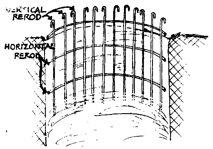
FIG. 8-1. REINFORCED CONCRETE LINING BUILT IN PLACE (a)
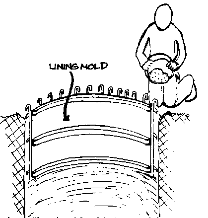
FIG. 8-1. REINFORCED CONCRETE LINING BUILT IN PLACE (b)
a. The hole has been dug to the required depth and rerod verticals stuck into the ground. The rerod horizontals are then tied to the verticals.
b. The inside lining mold has been centered and leveled. Concrete can now be poured around the rerod between the lining mold and the side of the hole. Also see Fig. 83.
3. Lower and assemble the mold.
- Level and center the mold. This is very important for the first section.
4. Pour concrete behind the mold (see Fig. 8-lb) and on all sides of mold to evenly distribute and not displace the mold. Gently tap around mold with a hammer to settle the concrete and prevent honeycombing.
5. Leave the mold of first pour in place
- Dig beneath it to a depth of a mold plus 10 cm (815cm) (If 1 m mold, dig 1.1 m; if 1/2 m mold, dig 60cm)
- Check diameter and plumb.
6. Assemble the re-rod in place.
- Tie the top of the vertical piece to the bottoms of the pieces extending out below the previous pour.
7. Lower and assemble the mold (another one, or the drop mold used in the first section)
- Level and center the mold.
- There will be a 10 cm gap between the top of the mold and the bottom of the previous pour through which to pour the concrete.
8. Mix and pour the concrete behind the mold.
9. Continue as in second meter.
After the mold is placed for the third pour, plaster the joint between the first and second pours with mortar for a smooth continued surface.
A more specific work plan for each of these steps is given in the next section.
Dig-a-Meter, Pour-a-Meter: Work Plan
1. Dig hole to desired depth
- Check diameter and plumb.
- Determine depth of hole, as follows.
When you dig the hole for the first one meter section to be poured,the actual depth of the hole will depend on 1) how much of a headwall you wish to include as part of the first pour, and 2) how you can best leave 25 cm to 30 cm of each vertical re-rod beneath the pour in such a way that they will not be embedded in the concrete. This will later be connected to the next lower pour.
Here are various headwall options for your consideration:
- No headwall
The depth of the hole is the height of the mold so that the pour will be flush with the ground surface. (See Fig. 8-2.)
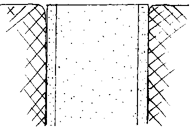
FIG. 8-2. NO HEADWALL
- 10cm headwall
The depth will be 10cm less than the height of the mold.
- 50m headwall
You will need an optional 50cm exterior headwall mold. The depth will be 50cm less than the height of the mold. For a 50cm headwall the mold should be 1m high. Assemble the normal 1m re-rod cage in place. The cage will extend almost 50cm above ground. Place, level and center the interior and exterior molds. The tops of both molds should be approximately even with the top of the re-rod slightly (3cm) below that. The width of the headwall is determined in the same way as the hole diameter.
2. Assemble re-rod cage in place.
The total height of the vertical re-rods should be (mold height) + 20(re-rod diameter)+ 10cm (for space to pour concrete between pours) + 10cm (for one 5 cm hook on each end of the rod).
For example: When using a one meter mold and 8mm re-rod verticals will be 1 meter (mold height) plus 0.16m (20x8mm re-rod diameter) also .10m (for concrete pouring gap) plus .10m (2-5cm hooks). The verticals will be 1.36 meters long.
- Normally use about 15 vertical pieces although you may need up to 30 pieces in very loose unstable soil.
- Bend over a 5cm hook on one end of each vertical re-rod.
- Space re-rods evenly around the hole. Push the unbent end of each re-rod about 30cm into the ground or until the top of the hooked end is about 3cm below the top of this poured section of lining.
- These re-rods should all be pushed into the ground where they will be approximately in the middle of the lining thickness. (See Fig. 8-3)

FIG. 8-3. PLACEMENT OF RE-ROD AND FORM IN HOLE
- If the ground is too hard to push the re-rod straight down, then dig down far enough to provide space for the bottom ends and fill the hole back in to the desired depth. However, this may waste time and effort that could be used more economically by digging the hole deeper before you line it. (See an alternative sinking technique on p. 86.)
- You will normally need 3 horizontal reinforcing rods per meter, although in loose soil 4 horizontal re-rods are better. These will be circles of re-rod with a diameter slightly less than the hole, they are usually placed on the outside of the verticals.
- To compute the length of re-rod which will need to be bent into the proper size circle for use as a horizontal reinforcing rod, used the following formula. The complete lengths of the re-rod will be the distance around the circle at the point where the re-rod will be placed, plus the length of the re-rod overlap, plus the length of the hook on each end of the re-rod.
[( hole diameter) -(lining thickness)] x 3.1416 + 20(re-rod diameter) + 2(5cm end hooks = length of horizontal re-rod
Example: For a well with a hole diameter of 1.5 meters with a lining thickness of 7.5cm (.075m) using 6mm (.006m) re-rod, the computation would look like this.
[(1.5) - (.075)] x 3.1416 + 20 (.006) + 2 (.05)
[1.425] x 3.1416 + 0.12 + 0.10
4.48 + 0.12 + 0.10 = 4.7 meters.
- Horizontals should be evenly spaced in each meter; for example, if there are three horizontals, one is placed in the middle of each meter; the other two are placed 37cm away on either side. (See Fig. 8-3) Be sure to include the 10cm or 15cm gap between successive poured sections if applicable in the computation of the length over which the horizontal re-rods should be evenly spaced. Tie all intersections of horizontal and verticals; make sure the re-rod is no closer than 3cm to the hole wall. Put pieces of stone or dried concrete between the rerod and the hole wall where it is necessary to ensure spacing.
NOTE: Instead of using a certain number of horizontal pieces, you can also use a continuous spiral re-rod which circles the hole 3 or 4 times per meter depending on how strong the lining must be.
3. Lower and assemble the mold.
- Lower the mold sections into the well and assemble them in place.
- It is also possible to assemble the mold above the ground and lower it into place.
- Center the mold in the hole making sure that it is level and that the distance between the mold and the hole wall is the same all the way around the hole. (See Fig. 8-4.)
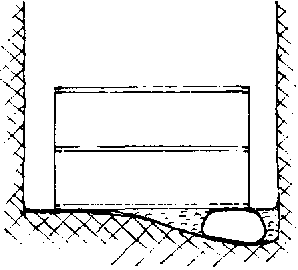
FIG. 8-4. MOLD LEVELED AND CENTERED
- It is very important that the mold be correctly centered and leveled for this first section because all of the other pours must line up and be attached to it. If the first poured section is not aligned properly all subsequent sections, if followed from the first one, could magnify that error and cause the well shaft to curve or angle out of plumb as it is sunk.
- Especially with the first meter it is often a good idea to check the level and centering again, just before the concrete is poured, to make sure that it has not been disturbed.
4. Pour concrete behind mold.
- Concrete is mixed on the surface (See Cement Appendix, p. 221.) and lowered in buckets down to workers in the well who will pour the concrete behind the mold.
- When pouring concrete behind the mold, do so from alternating opposite sides of the mold. If you continually pour the concrete into one spot or unknowingly concentrate on one side of the concrete, it will soon build up enough weight that it will move the mold off center or out of line. Once that happens it is virtually impossible to move the mold back to its intended position. (See Fig. 8-5.)
- Once the concrete is poured, gently tap around the inside of the mold with a hammer. This slightly vibrates the concrete so it settles into any voids that may have been left while pouring. After the concrete has set in an hour or two, you can begin working on the second pour.
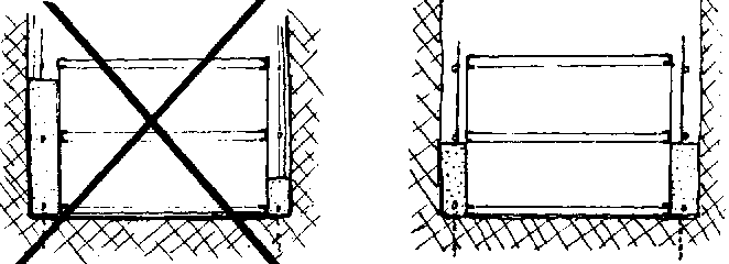
FIG. 8-5. POURING CONCRETE EVENLY IN PLACE AROUND MOLD.
5. Dig hole beneath the first poured section
The depth of this dig should be the mold height plus 10 cm for a gap between the bottom of the first poured section and the top of the second pour through which you will pour concrete. (See Fig. 8-6.)
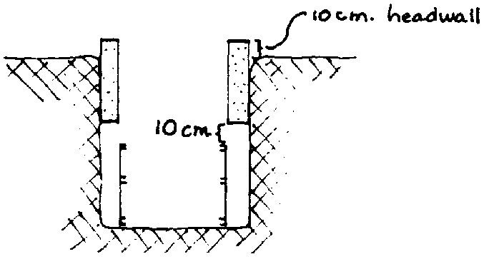
FIG. 8-6. PROPER HOLE DEPTH BENEATH AN ALREADY POURED LINING SECTION
6. Assemble reinforcing rod in place
Bend a 5 cm hook on the bottom ends of the re-rod extending down from the previously poured section.
Place the horizontal pieces in the well; pull the horizontal pieces up into place and tie all intersections with horizontals.
Assemble the same number of vertical pieces as in the first pour.
Bend a 5 cm hook on one end; stick the unhooked end into the ground 25-30 cm directly beneath the verticals of the previously poured section and inside the horizontals lying on the ground,
Connect the verticals to the previous verticals with sufficient overlap, twenty times the diameter of the rerod, and a 5 cm hook at either end of the overlap.
Place the horizontals as in the first pour. Make sure the re-rod is no closer than 3 cm to the hole wall.
7. Lower mold into place
If you have only one mold, remove and lower it from the previously poured section.
This way it is possible to dig and line about 1 meter each day in soil that is easily dug. A single mold should be cleaned and oiled at least once every 3 meters,
During the one day that each poured concrete section sits while the following section is dug, it will set sufficiently to enable the mold to be carefully removed. (See Cement Appendix, p. 221.)
If you have more than one mold you may leave them in place until needed for constructing subsequent sections.
Center and level (plumb) the mold.
8. Mix and pour concrete behind mold
Don't forget to alternate sides for pouring each successive bucket to allow the concrete to settle evenly.
9. Successive pours
- Continue as in second pour;
- Fill gaps between pours with mortar when the molds have been removed from both sections.
D. Dig-and-Line-in-Short-Sections
This lining method involves digging the hole to some convenient depth and then lining it. Once the lining for that section is complete and is anchored in place, continue digging the hole beneath the already lined sections. These sections are dug and lined until the water table is reached. The depth of each section can be whatever you feel comfortable with both from the point of view of safety and work convenience.
1. Dig hole to certain depth
Dig a hole until you reach a depth where you feel it might be unsafe to continue, or until you have sunk the hole a maximum of 5 meters. Depending on whether you want a headwall and, if so, on the height you want it to be, you may want to slightly change the hole depth so that the top of the mold will be at the desired top of the headwall after a number of poured lining sections are completed.
2. Assemble re-rod cage in place
- Where possible, use single long pieces of re-rod for verticals. These can be anchored to the hole wall with short pieces of re-rod bent into hooks and pounded into the hole wall around the verticals.
- Put horizontals in place, beginning at the bottom and working up.
- Tie each horizontal in place temporarily with enough ties to hold it in place. This allows for any adjustments that might be necessary later.
- Before the mold is put in place for each pour, securely tie all of the intersections of horizontals and verticals.
3. Lower and assemble mold
- Level and center the mold in the bottom of the hole.
4. Pour concrete behind mold
- Leave the top surface rough for a good bond to the next pour.
5. Lower and assemble another mold
- Set it directly on top of previous mold;
- Pour concrete behind mold;
- Repeat this step until you reach the ground surface or bottom of the previous set of pours.
6. Repeat steps 1 through 5
- Repeat these steps until water is reached. The bottom of the lining should be constructed with a curb just above the water table.
NOTE: If you are digging and lining beneath a previous lift be careful to leave enough room between the top of this lift and the bottom of the previous lift through which YOU can pour concrete (See Fig. 8-6.)
E. Dig-down-to-Water-Table-and-Line
This method is recommended only where the water table is within a few meters of the earth's surface and the ground is firm. It is included here to demonstrate that the same operations must always be performed although, depending on the depth, they may be done in a slightly different order:
1. The hole is dug down to just slightly above the water table,
2. Dig out a curb at the bottom of the hole.
3. Assemble the re-rod in place.
4. Set the form in place. Remember to carefully center and level the form.
5. Mix and pour the concrete into the form.
6. Continue lowering molds on top of previous molds and pouring concrete behind them until you reach the ground surface.
F. Pre-Cast Reinforced Concrete Rings
Pre-cast reinforced concrete rings are often used to line wells. They are poured and cured above ground to be lowered into the well later. There are two basic methods for installing rings:
lowering and stacking them in an already dug well: (See Fig. 8-7.)
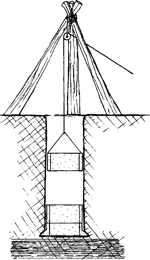
FIG. 8-7. LOWERING PRE-CAST CONCRETE RINGS
setting them in position at the ground surface and sinking them into place. (See Fig. 8-10.)
Rings should be made so that they:
can be easily stacked or attached one on top of another;
can form a watertight joint where they meet;
are strong enough to support weight of a long column of rings;
will not rot, corrode, rust or otherwise lose any of the above qualities;
will not react with water to make the water less desirable for consumption.
This method is more useful in a large project where rings can be centrally manufactured and then transported to the well site for use.
Making your own rings will require the use of inner, outer, top and bottom forms. The inner, outer and top forms can be carefully removed after the concrete has just started to set, usually in an hour or two, making it possible to Make several rings each day if enough bottom forms are available. Where a number of forms are available,it is better to leave them in place to allow the concrete to cure better.
You can 1) make your own reinforced concrete rings or 2) sometimes obtain them on the local market as culvert pipe or a similar item. Both are suitable.
Determining how two rings fit together is a major concern when lining a well with concrete rings. Frequently flat edges have simply been mortared and stacked on flat edges. (See Fig. 8-8a.) This provides very little resistance if an unequal sideways force is exerted. A tapered or flared fit is better. (See Fig. 88b and c.) These will resist sideways forces better and should be arranged so that water flowing down the outside of the lining will tend to flow away from and not into the well. Where possible, the two rings should be firmly attached together. This is most often done with nuts and bolts through steel fittings cast into the rings. This type of connection is especially useful when the lining will be sunk into place but may not be necessary when stacking rings in an already open hole.
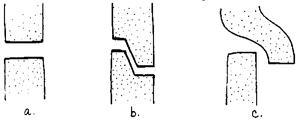
FIG. 8-8. CONCRETE LINING RING JOINTS
As with most other concrete casting techniques, the concrete in the rings can either be made watertight or porous. Porous concrete rings can be especially useful when sinking the lining into the bottom section of the well.
1. Stacked in open hole: Work Plan
- Dig curb slightly above water level;
- Reinforced the curb and pour it around a form in such a way that a lining ring will sit on top of it. (See Fig. 8-9.)
2. Lower ring into place on top of curb.
- The major problem with lining a well this way is that there is very little adhesion between the lining and surrounding soil.
3. Continue lowering rings and filling in around them until you reach the ground surface.
NOTE: It may be useful to install curbs or some other type of anchoring to help hoed the column in place.
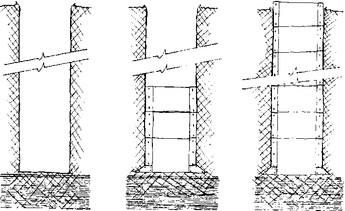
FIG. 8-9. LINING RINGS LOWERED INTO PLACE ON ANCHORING CURB
2. Sunk from ground surface: Work Plan
This involves stacking rings as necessary on a cutting ring while the whole column is sunk by digging out soil from inside and underneath the bottom of the column. Because of its complete protection from caving this method is used in very loose soils that would be difficult to keep the column going out of plumb, especially in loose soils. The problem is compounded by the fact that once the column begins sinking askew it is very difficult and sometimes impossible to get it straight again.
A cutting ring is a special ring that provides a cutting edge to help sink the column and also helps to funnel soil directly underneath it into the middle of the hole for removal. (See Fig. 8-lOa.)
1. Set 1 or 2 lining rings on top of the cutting ring. The more rings you can stack, the more weight the column will have and the easier it will be to sink. However, the rings are very heavy and it will usually be very difficult to lift the rings any higher than 1 meter with locally made equipment.
2. Workers will stand inside the ring and dig to remove soil and permit column to sink. (See Fig. 8-lOb.)
3. Digging should be done especially carefully to try to remove soil evenly from around the bottom of the hole so that the column will sink plumb.
4. Add more rings when the existing column sinks down to where another ring can easily be added (usually about ground level or just above). (See Fig. 8-lOc.)
5. Continue sinking the column and adding rings as far as possible into the water table. (See Chapter 9, p. 99.)
NOTE: Because of the strong possibility of rings sinking askew and the uneven forces that will often have to be applied to the column in order to get it straight again, it is a good idea to have the rings firmly attached to one another.
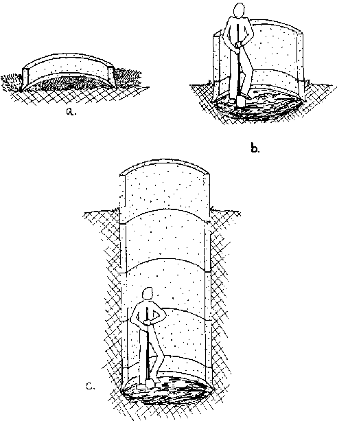
FIG. 8-10. SINKING LINING RINGS
Often in loose soil, mostly sands, the rings sink askew, which causes problems, especially when the thickness of the loose layer is about 4 m or mole. In less thick layers (about 2 m) the best way to sink the column relatively plumb is to continue digging as fast as possible until firmer layers are struck. Even if the rings are standing askew, they may be put in an upright position again as follows.
If the rings are askew, as in Fig. 8-lla, work inside the column of rings to remove the soil from beneath the lowest edge of the bottom ring as shown. The hole you dig should extend underneath and beyond the outside edge of the ring. When this is completed, carefully dig the soil away from beneath the opposite side of the column but, on this side, try not to dig any further out beneath the ring than absolutely necessary. (See Fig. 8-llb.) As the column sinks from this point, it should gradually ease over toward the side that was first dug out. (See fig. 8-llc.)
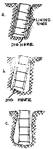
FIG. 8-11. STRAIGHTENING A COLUMN THAT HAS BEEN SUNK OUT OF PLUMB
G. Mortar (plaster)
1. Cast in place
Reinforced mortar is used much like reinforced concrete. The major advantage of this method is that no forms are required because the mortar is thrown onto the wall in place.
This variation evolved in Senegal. It was difficult to transport heavy steel molds to the well sites,so the masons would "throw" the concrete onto the walls. But concrete is not very workable so the masons began leaving out the gravel and using just mortar.
Walls are normally plastered meter-by-meter as the well is dug. This is a variation of the "dig-ameter-poura-meter" method used with reinforced concrete.
This process is as follows:
1. Dig the hole about 1.1 m deep.
2. Check the hole diameter and plumb.
3. Cut and shape as much re-rod as possible beforehand because the next steps must be done quickly.
4. Splash the mixture (1:4, cement: water) on all surfaces to be plastered. If the surface dries too quickly, wet it again immediately before plastering.
5. Apply a 3cm thick layer of mortar with a trowel.
6. Place the re-rod.
7. Apply second 3cm coat of mortar while the first is still wet.
8. A third, thinner layer may be applied to make the walls as smooth as possible.
2. Pre-Cast
Mortar can also be used to pre-cast rings even where forms are not available.
1. Dig a round hole with the desired outside diameter of the ring. (See Fig. 8-12a.)
- The hole's depth will determine the height of the ring.
2. The hole is then plastered and reinforced just as it would be in the well. (See Fig. 8-12b and c.)
3. After it has cured for several days it can be dug up and later installed in the well. (See Fig. 8-12d.)
- This type of ring should be allowed to harden for at least one week before it is placed in the well.
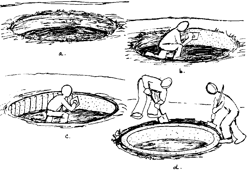
FIG. 8-12. CASTING CONCRETE RINGS IN EARTH FORMS
H. Mortared brick or stone (masonry)
Rock has been used to construct linings in wells for centuries. Construction of a well using rock usually involves digging the hole as far as possible into the water table before the lining is built. Once the foundation under water is established, the walls are usually built up in a double layer about 50 cm. thick. Rock walls are very weak in tension so they can be easily cracked if any uneven stresses are put on them.
This type of well can provide acceptable quality well water if precautions are taken to prevent contamination from surface water seepage through the lining. A 5 cm. thick layer of concrete or mortar around the top 3 m. of the lining can prevent the seepage of contaminated surface water back into the well. In fact, the surface water seepage may eventually reach the water table and find its way back into the well, but if this seepage has been filtered through at least 3 m of soil, the potentially harmful contaminants will have been removed. (See Fig. 813.)
Brick or stone masonry can be used in most of the different digging and lining methods but, because of its tendency to crack under stress, it is not normally used except to build the lining from the bottom of the well up, in one continuous operation.
A brick or rock wall can be built up on a cutting ring and sunk into the ground (See Fig. 8-14.) but any caving around the outside could crack or topple the wall. If such a column were to sink askew it could be very difficult to get it upright again without exerting some kind of sideways force on the column which could crack or destroy the column.
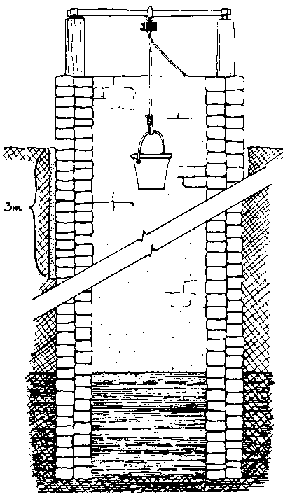
FIG. 8-13. ROCK LINED WELL 3m OF CONCRETE OR MORTAR SEAL IS TO PREVENT CONTAMINATION
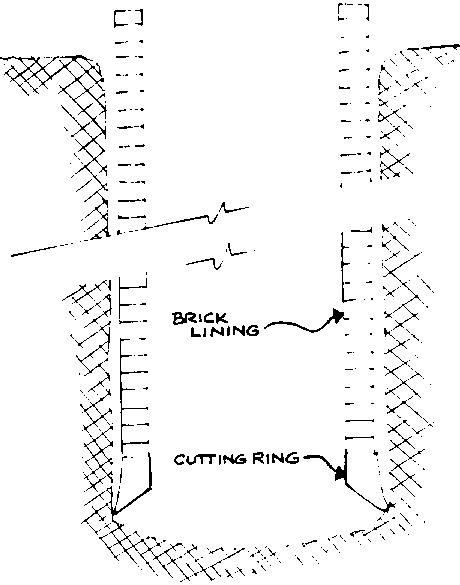
FIG. 8-14. BRICK LINING SUCK ON A CUTTING RING
It is possible to use reinforcing rod to help hold a brick lining together. This is sometimes used in sinking the bottom section of a well. It is not normally used for construction of the middle section because in most cases a reinforced concrete or mortar wall could also be built with the same materials, and provide a stronger lining. (See Fig. 815.)
It is also possible to use masonry to line the wall in sections. When a lining is needed after having dug down a number of meters, a curb can be installed and the lining built up on the curb. The curb serves as a base on which the lining can be built up and as a solid anchoring piece which can be supported to allow digging to continue beneath and through it As a safety precaution, the curb should be supported by long pieces of wood, or whatever else is available, which can be wedged between the bottom of the hole and the curb. (See Fig. 8-and the curb. (See Fig. 8-16.)
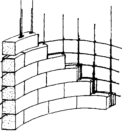
FIG. 8-15. REINFORCED BRICK LINING
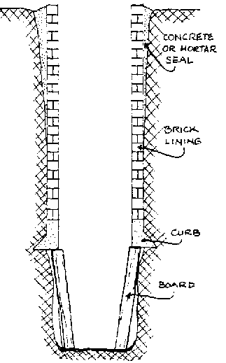
FIG. 8-16. SECTION OF BRICK LINING

